- Sign In Changes: You now need to sign in using the email address associated with your account, combined with your current password. Using your display name and password is no longer supported.
- If you are currently trying to register, are not receiving the validation email, and are using an Outlook, Hotmail or Yahoo domain email address, please change your email address to something other than those (or temporary email providers). These domains are known to have problems delivering emails from the community.
Leaderboard

Popular Content
Showing content with the highest reputation since 07/21/2025 in all areas
-
Forum has been restored and secured for now. Further safeguards will be put in place soon. In the coming weeks software updates will also take place. An exact timeline has not yet been determined, but some of this work may result in the forum being offline temporarily.5 points
-
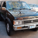
I'm the second owner of my pretty much stock 03 Pathfinder SE (auto, part-time 4wd) since 2015. Things happened in 2020. Decided to convert the Pathfinder to manual. Bought a manual trans from a 2002, took my time, and in summer 2023 finished rebuilding it. Not including that here as it's pretty routine - all new synchros, bearings, input shaft and some gears that had chipped teeth, then back together. If you have a 2000, 01 or 02 part-time or rwd you can swap in a manual, get a manual ECU, (deal with NATS), and be done. (You can't manual swap a full-time 4wd, fulltime unit only works with an auto) My problem with the 03 was Nissan discontinued manuals in the US in late 2002 for model year 2003, which also had new revisions with a more advanced ECU including electric throttle body and other changes. So I could either go 'backwards' to a US 2002 manual ECU and install throttle cable, find a wrecked US manual truck and swap everything across - or get an 03 manual ECU and make it work. I didn't want to go backwards. I'm also in WA which doesn't do smog checks so no issues modifying or mixing and matching. Luckily, Nissan still sold the 03-04 as manual in Canada. Looking at parts diagrams in Amayama it looked like the Canadian auto 03 model was near-identical to the US model, so the manual couldn't be that different, I figured. The worst outcome was it wouldn't work at all, or that I'd have to keep spending money until it worked or I gave up. I took the gamble. I reviewed the earlier Pathfinder auto to manual guide linked on this forum, and also looked up a lot of 350Z conversion forums as it's the same engine and ECU. Also Nissan Skyline and 300ZX forums as different engine, but same transmission. I found the throttle body changed part numbers in 07/2002 from cable to electric, so that was the cutover date. Anything after that was right. I searched individual junk yards in Canada until I found a place selling a clutch pedal and bracket, ECU, and flywheel. The tell with the 'right' car was there were no throttle/cruise cables in the engine bay pics, cuz electric throttle. The yards that had what I needed were in rural Alberta. Apparently Alberta has a lot of R50 Pathfinders in their yards. I mainly used car-part.com. I sent the ECU away to get NATS disabled so I wouldn't need to deal with it. Got everything in and worked end of summer 2024, and wanted to share here. Pics and posts to follow once I get an image service set up.4 points
-
He has been an NPORA member for nearly 20 years and a regular the whole time. Recently he worked with us in the background to get the forum back online, root out problematic DDoS sources and test for reliability. And now adamzan has agreed to join the Mod Team. Welcome adamzan!4 points
-
I have not yet been given an actual cause for this nearly week long outage, but after spending hours on the phone with the host company today, repeatedly reminding them that they had assured the site would be back up before this past weekend, here we are back up and running... finally! edit: Turns out the host utilizes AWS facilities, so this was related to the major AWS outage that occurred at the same time. Don't know why they couldn't just say that from the beginning.4 points
-
First things first - remove the transfer case Lots of extensions needed to get to bellhousing bolts. I bought proper long ones after this. Auto transmission detached Flexplate Flexplate removed Source of my rear engine oil leak (after clean up) - rear pan seal job was badly done Sealed it up good. Also I didn't take a photo, but you need to remove the steel inner collar. It's a total pita to get out. It centers the torque converter, but the manual transmission uses a small brass one. There's videos online, the 350Z auto to manual conversion videos cover it. I couldn't get it out for hours and broke various tools, I thought that was the end of the project. But I got it out eventually with the exact right sized puller. Fortunately the R50 chassis has the clutch master cylinder hole already there under a plate Turns out the auto trans computer sits on the other side of the clutch blank plate so both come out at once Factory clutch master cylinder. I thought about steel clutch lines, but ended up using an ebay 240SX clutch line kit. Works fine.3 points
-
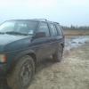
Pulled it out to give it a wash today.3 points
-
3 points
-
Good day everyone, one morning I was on market place and found a VG33ER forsale for a decent price and for a and was a good few hours drive but I picked it up with no prior intention of swapping my pathfinder. The swap is pretty straightforward along as you have all the parts from an ER to swap. It is also 02 Xterra ECU swapped on the original body and engine harness. The pulley is swapped now as of writing to the 4x4parts 2.4 quick change pulley on the stock SCB cut off. It makes a significantly more amount of power than before and is absolutely worth it if you can afford the premium gas. ALTHOUGH, it seems the MPG has been improved since the swap at least at partial throttle which is pretty cool. It's also running factoy R50 airbox with all original sensors. Here's what was swapped Lower intake Injectors Fuel rails (minor differences) Supercharger Spark plugs Spark plug wires Thermostat 180 to 170 AC tensioner only NOT alternator Belts Crank pulley Water and ps pulley NOT alt ECU and plug Pas side valve cover (only for PCV valve) To swap the ECU most of the pins are in the same locations how ever not all. you WILL have to solder a larger pin on the orange IACV wire and to make the SCB safety work you can reuse and replumb the map/baro switch as the SCB and it works the same. All valves, sensors and anything else are original 97 pathfinder. You will have to run different length belts for all 3 now that the V belt is deleted, the crank and water pump are different size and the super charger belt needs to be a 5 rib and shorter unless you swap the AC comp. Cruise even works too! It drives incredible and I could not be more happy with the result. before the pulley it feels like a more peppy VQ but after the pulley it pulls harder than one for sure. When I dump the clutch I'm always first off the line even to the diesel guys that book it off the light (i'm looking at you Dodge owners) and it seems to run cooler than my friends bone stock X since mine has a hole in the hood and gets good cooling. Thanks. Donor engine in back of my r50 On floor after getting it home repinning the ECU plugs Cleaning Radiator shows up Installing charger and intake *borart voice* VERY NICEEE2 points
-
Rock auto has reman and some new off brand ones that are decent just don't get the cheapest of cheap sometimes those aren't that great. GB stuff is pretty good from what I've heard never tried it personally though Also, you only need 1 post you don't need to add to multiple sections of the forum2 points
-
Just incase anyone needed to know, you CAN fit a fully dressed VG33ER in the back of an R50!2 points
-
Here's a link to the service manual. Page 196. basically warm, then hold no load 2k rpm for 2 minutes then check timing in N should be about 15 degrees +/- 22 points
-
I have an extra distributor that I marked core. I have had it so long I forget why I marked it that way. I figured I would try and put that one in and see if the issue goes away. The issue went away. I couldn’t get it any closer than 17 degrees. That’s within the range the manual gives. I am relieved to know that it should be the distributor. I will get an another one and cross my fingers that it fixes the problem. I will report back after the new one is installed.2 points
-
The manual transmission chassis cover plate was unavailable, so I cut the existing one to fit the manual shifter The service manual says to fill the transmission from the shifter hole, so I did Intermediate covers and soundproofing Manual transmission trim installed The original auto transmission connector block. I connected up the neutral position switch to the PNP relay so it only starts when the shifter is in neutral. And connected up the reverse lights, just four wires2 points
-
I made an adapter for my transmission jack to securely hold the manual transmission in place. I've used ordinary jacks to reinstall car transmissions before but this thing is pretty heavy even without the transfer case and I didn't want it falling on me About to go in Lining up manual transmissions just right to install is always annoying. Sometimes you gotta take it completely back out and down and start again. Sometimes it pops right in You can see the innards of the transmission before the transfer case is attached. Without sealant the transmission oil would all seep out Technically the manual transmission transfer case is different - it has a small gutter under the input shaft, and subgears to absorb shock. But nothing that is needed for the conversion. The auto transmission transfer case works fine. But you have to apply sealant as the back of the manual transmission is open2 points
-
A pic of the back of the new flywheel showing 03-04 signal plate A view of the clutch fork from the outside. It pushes towards the engine, which pulls the pressure plate 'off' the clutch and flywheel2 points
-
So first I tried a 350Z flywheel - but it was too high and wouldn't allow the pull clutch to work so couldn't release the clutch. So pulled the transmission out again, and next I installed a US '02 flywheel But the signal plate is way different, it's for the cable throttle ECU and the engine wouldn't start 00-01-02 signal plate on left with like 300 or something holes. 03-04 signal plate on the right. The right side has 3x 10 holes. That's what I needed, but flywheel not flex plate I found I needed part number 123105W90A (03-04 only) which is unique to the R50 Pathy due to the pull clutch. It was hard to find but found one in the UAE from I think partsouq Correct flywheel installed I found the starter motor had to be shimmed back about a 1/2 inch otherwise starter gear would hit the flywheel. There's an official part number for this, a plate the starter sits sandwiched under, but it's out of stock so I just used washers OEM clutch plate is an Exedy Pressure plate installed It's pretty big as pressure plates go, but the pull clutch means the clutch pedal is light (is why they chose it for the Pathfinder - more grab but lighter to use)2 points
-
Clutch pedal installed. I couldn't find a Pathy brake pedal - probably because its bracket wraps around the steering column. I kept hitting the brake when I went for the clutch, so I ended up just cutting the brake pedal the same size as the clutch pedal and it looks factory now You can't really see, but the clutch pedal bracket goes where the auto trans computer used to be. It has a clutch starter switch but I didn't connect it (did connect the neutral start switch though) The Pathfinder manual uses a pull clutch (not a regular push clutch) which I had to figure out how it works Got the OEM parts Assembled. It 'clicks' into the pressure plate on installation. Then to release you pull out that pin, and the fork falls out. You lift the collar on the clutch release bearing to release it from the pressure plate. It's kinda hard to explain without seeing it in action.2 points
-
I had never rebuilt a manual trans before. Followed the service manual, "Beer Garage" (since deleted), and youtube videos and took my time. I used a toaster oven to make dropping the press fit gears back on easier. I bought a factory shifter. But I thought it was too tall so I cut about an inch off it and welded. I am not a professional welder at all. But it has held up fine. I also found and bought a NOS Pathfinder clutch, and a 350Z flywheel. I figured a 350Z is the same engine and clutch, and the clutch and flywheel fit together. Seemed so far so good.2 points
-
My one tip is to make sure you can get the fill plug loose before draining the oil.2 points
-
I'm running a Magnefine on mine as well. I don't know that it's strictly necessary, but I wanted to give my high-mileage slushbox every chance I could, especially after seeing a little glitter in the fluid when I flushed it. I routed the lines on mine so the fluid goes from the trans, through the stock cooler in the rad, through the aux cooler, through the filter, then back to the trans. My thinking was that the OE cooler can only bring the fluid temp down to the coolant temp, so it should be the first stage. I put the filter on the return side just in case the cooler (which was not new when I installed it) had some schmutz in it. That I don't know. But I've had the filter on mine for the last 30k miles, and it hasn't complained.2 points
-
Finally got this engine built New pistons, Rings, Bearings, Timing Chain, guides, tensioner, Water pump, clutch, plugs, leads, oil pump First Start on Thursday, Yesterday I took it around the block, got a heat cycle through it then retorqued the head, set valve clearances and dialled the timing in. It sounds and feels great! Ready for the next 500,000 hopefully!!2 points
-
well got it all on the ground yesterday and drove it around. gotta get the alignment done, new tierods, rack bushings and possibly another set of camber bolts. I have everything in the garage but just ran out of time. Also front diff isnt in since pinion seal is trashed and i think its leaking behind the passenger axle. may just source another diff from the junk yard. Otherwise it drives around! just got to get these AC coils and 9446s to settle in and well be good! https://imgur.com/3XhUaw5 https://imgur.com/6QKYQiV2 points
-
I know a lot of people like to delete stuff like those lines but the truck just runs better when you don't try to engineer it yourself lol.2 points
-
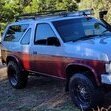
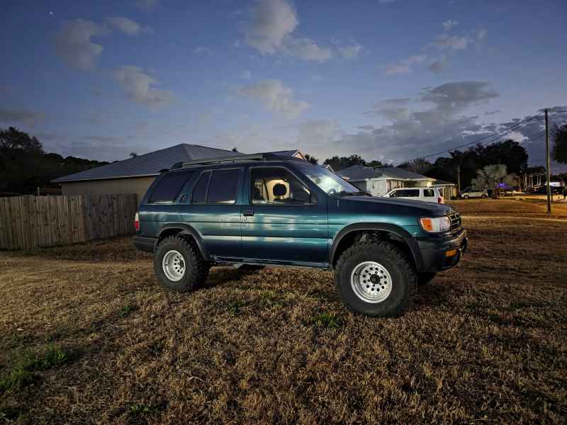
so little update. Got my SFD ordered back in like november and it showed up in december BUTTTTT the lovely people at UPS messed up the box quantity with item quantity and the tariffs/duties skyrocketed to 2400 bucks per box. which means 4800 for 2 boxes with 500bucks worth of parts in them lol so its been re routed back to the shipper in canada and is currently "lost" per ups but they found it in montana. It has been an absolute shyt fest and waiting. So in the meantime i put on some 2in AC coils from 4x4parts and debating on if i want to rip the trans out of it to do the clutch now and replace the input shaft bearing since it is howling and making all kinds of racket. Heres a pic of the truck last night after i did the coils
 2 points
 -
yep ! that's a good guy ! happy that the forum is back online... facebook groups are just not my thing when you search things ! way to go adam2 points
-
Thanks! Glad to help out.2 points
-
Not able to upload photos with insert image 2" AC coils with 4" SFD, kyb struts, missing link, LR RKB101060.C8 about 6 inch rear lift, Bilstein 5125 33-185569, Warn Hubs, -3.75 backspacing, 33x12.5R15 Duratrac Wrangler, tire carrier with full size spare https://imgur.com/gallery/AIvp4br2 points
-
Okay, so I figured out why I was having such an issue. It was the wrong seal. Sigh.2 points
-
Well (expletive.) Thank you for the info. I have been turning wrenches for maaaany years and my brain did not put those two together. Totally makes sense. Thank you for knocking the cobwebs off of this old head. Checking out HPS now.... WOW. How have I not found this before. Thank you dudes!!! I owe you both a FEW beers....2 points
-
Alright, got it through emissions and re-registered! Only 8 months late... Last night I installed a non-fouler on the downstream driver's O2 sensor and it seemed to do the trick. Not only did the P0430 not move to stored to screw up my day, but it's also no longer in pending. Steering was a little more squirrelly today. I need to get to the bottom of that. But otherwise, the truck is operational. Hoping to do a shakedown run soon.2 points
-
https://hpsperformanceproducts.com/ Not the cheapest thing, but I intended to never have to deal with it again Silicone is fine for vacuum lines and coolant lines (reinforced in the latter case for the pressures) but also worth noting can be more difficult to seal at the ends (hence I use coolant-exposure-rated RTV for added insurance). It's true different kinds of rubber - of which at this point there's so many I've lost track - are good for different kinds of things and will fail if mis-applied. Here's my cheat sheet: For fuel hoses, I replaced everything with Gates Barricade except for the submerged hose in the tank/pump which was some super special snowflake stuff (fuel submersible rated) - and wildly expensive. Crankcase ventilation/PCV - Gates PCV/EEC Vacuum/Coolant - (reinforced) silicone as noted2 points
-
Look for a manual car wash, the kind that eats quarters and gives you time with the spray wand. Don't shoot it directly at electrical connectors or fluid caps if you can avoid it, otherwise give 'er hell. I'd spray it down before you get in there. It's much nicer working on something that isn't an oily mess.2 points
-
Rat Trap's steering wheel was starting to get gross. Hand sweat, sun damage, and the previous owner's lung darts had left the outer rim cracked, turning brown, and starting to smell. Then I remembered that aftermarket steering wheels are a thing. Maybe the minitruckers are onto something, I thought. I figured I'd keep things simple by going with a wheel and a column adapter from the same company. Grant's website showed an adapter kit for these trucks, #3560, so that was a good start. I had a look through their catalog and decided on their #1160. Simple, black on black, leather grip. No rainbow chrome, no trucker babes, no flames. http://www.grantproducts.com/images/product-images/lg/1160.jpg Summit had it well below list price, so I ordered it from there. They didn't have the column adapter, and Grant's website's checkout didn't work, so I ordered that from elsewhere. The folks I ordered the column adapter from emailed me the next day to say that they didn't actually have one. I checked around, and found a bunch of other retailers listing them as discontinued or out of stock. The few who claimed to have them either didn't get back to me or confirmed that they couldn't get them either. Grant's site also listed a fancy billet adapter, #5560, but I couldn't find one of those, either. There are a bunch of cheap D21 column adapters on eBay. They're all drilled for six-bolt wheels. And the #1160 wheel I had ordered, which by this point was already in the mail, is five-bolt. Nissan Nut's page suggested that Grant #3596 would fit instead. I found one on eBay. It came in an "American Products Company" box. (Made in Taiwan, naturally.) It doesn't say Grant on it anywhere, but it looks just like the Grant kits, the splines are correct, and the three-bolt pattern matches the spacer. Is it a knockoff? Is this Grant's own off-brand? It's what I could get. The wheel came with a spacer. The spacer adapts between Grant's three-on-1.75" pattern (which the column adapter uses, as do some of their simpler wheels) to their five-on-2.75" pattern, which their "Signature Series" wheels (including this one) use. It's made from welded steel, and it feels sturdy. Unfortunately, it spaced the wheel too far back, to where I had to reach for the lights and wipers. It's also stuffed into a rubber sleeve, which doesn't fit it very well. Flipping it around doesn't help, either. Either it's so loose at the front that you can see the metal part of the spacer through the wheel, or it's so loose at the back that you can get your finger in between them. And it's tight enough in the middle that it gets stretched into a polygon by the spokes of the spacer. I suspect its primary function was to sell the billet adapter kits. Naked spacer in the middle, misshapen rubber thing on the right. On the left is the Forever Sharp MG15-B billet spacer that I used instead. It's half an inch shorter, which fixed the gap to the stalks, and it looks way better than the floppy rubber turtleneck. It actually looks quite nice! It also solved a dumb problem with the column adapter, which is that you need a special three-bolt puller to remove it. The Forever Sharp spacer is drilled for both 5 on 2.75" and 6 on 2.75", so you can bolt a standard wheel puller across two of the six-pattern holes to pop the hub assembly off the splines. (The holes are threaded #10-32, same as the Grant spacer.) Either spacer goes in between the column adapter and the nut. Unfortunately this leaves the end of the steering shaft slightly short of the end of the nut. I don't think it's going anywhere, but, yeah, I don't love that. I have yet to decide if it bothers me enough to take it back apart and do something about it, but I'm leaning towards swapping that nut for one that doesn't have a washer attached to it. The turn signal cancel mechanism fought me a little bit. The APC column adapter has two holes for roll pins, which take the place of the tabs on the back of the stock wheel. The pins aren't long enough to hit the cancel lever on the switch if you push them in all the way, which I found out the hard way. The second time, I installed them about a quarter inch into the column adapter. That sorta got them working, but, strangely, only in one direction. I figured the pins were just a little too close to the center, so they weren't engaging the cancel lever properly. To fix this, I removed the turn signal stalk (as pictured below), stuck a 1/4" extension in through that hole there, and used that as a punch to gently persuade the pins outwards a little. This might not be the right way to do it, but the signals cancel perfectly now. Actually, they cancel a little better than they did with the stock wheel. Round and square dash have different turn signal cancel mechanisms. Square dash has a single cancel lever on the switch, and two tabs on the back of the wheel, spaced about 120* apart from each other. Round dash has two separate cancel levers on the switch, with a space between them, so Nissan moved the tabs on the wheel out to 180* to account for that space. (Square dash wheel on top, round on bottom.) The APC hub has the 180* spacing of the round-dash, but my truck is square-dash, so the steering wheel has to turn 90* for the pins to hit the cancel lever (I think stock is about 60). I thought the factory setup was a bit trigger-happy, so I consider this an improvement. That rounded sheet metal cover came with the column adapter, and it doesn't cover it very well. It's got a pretty big gap to the clamshell. My clamshell is a redneck abomination of my own devising, so I can't say for sure that it wouldn't match the original clamshell a little better, but I know the stock wheel was not gapped out that far. Maybe the correct kit comes with a longer cover? I'll probably make up a new one that actually fits at some point, but today is not that day. I've read some complaints about the horn buttons on Grant's 3-bolt wheels. This wheel doesn't use that design. The five-bolt wheels use a self-contained horn button, which friction-fits into the trim ring. It's got two spade terminals on the back for the wires. One wire comes from the column adapter (which uses a piece of circuit board for the slip ring), and the other goes to a ring terminal, which I put under one of the three bolts holding the spacer to the column adapter. This system works just fine with the factory horn contact on the column, and I didn't have to modify or adjust anything to get it working properly. Sadly they don't have any amusing replacement horn buttons, or even a Nissan one. Just domestic brands, their own name, blank, or "4x4," in case you need reminding of that sort of thing. I've driven around a bit since installing the new wheel. The leather grip feels nice, and it doesn't have a rancid mixture of hand sweat and lung dart residue festering inside of it, which is a welcome change. The smaller diameter clears my knees better, but it's not so small that I feel like I stole the wheel off the riding mower. And I like the look--it looks upgraded, without looking like I've mistaken Rat Trap for a racecar. That said, the fit and finish could be better. There's a little glue residue on the spokes, the leather wrap ends closer to the spoke slot on one side than the other, and that one out-of-place white stitch at the bottom bugs me a little. The horn trim ring has a garf under the paint, and came with some paint scratched off around one of the screw holes--screw holes which mysteriously don't exist in Grant's product picture. The picture conveniently omits the spacer with the can koozy around it, too. So, yeah. This turned out to be a bit more of a can of worms than I had hoped, and if I was going to do it all over again, I don't know that I'd do all the same things. Now that it's all said and done, though, I like it, and it's staying. One last thing: I did reach out to Grant's customer support about the adapter. Grant's tech support guy confirmed that the #3560 kit was out of stock, but said he'd managed to track one down. (Naturally I had already ordered the other kit by the time I got that email.) So if you need a Grant column adapter, try their customer support--they may be able to hook you up.2 points
-
Haven't dealt with this on my Pathfinder fortunately, but did on my 98 Frontier. It sucked. Charcoal pellets all the way from the rear of the truck to the solenoid valve in the engine bay. My issue produced a P1444 (purge solenoid valve) but the codes in that series tend to be related, and in my case the code was brought about by a ruptured charcoal canister. Blowing and vacuuming the lines is not enough. The charcoal crumbs get jammed together in the lines. You need to use a stiff, but flexible, wire to push through every hard line, and it may be necessary to remove any hoses. Flush the lines with pressured water if possible, but house pressure is fine. Then continue to blow and vacuum the lines using whatever attachments you can to maximize pressure. Repeat this couple times. Any little charcoal crumb will eventually clog the line or find its way into the solenoid. My long term solution there was to put a transparent fuel filter on the line right off the canister. BTW, the solenoids can be fixed if they clog, since they're not cheap to replace. You just bend the little metal tabs in a little and split the coil portion from the plunger. Some pins/needles can dislodge pieces that are blocking the valve. The solenoids are also commonly used on other Nissans (the one on my 04 Pathfinder is identical to the one on my 98 Frontier). Not sure about the "405". What are you using to pull codes? Is the code exactly "P0405" on screen? Reason for asking is because in 98, you could pull "codes" directly from the ECU without a scanner, but the code it flashed was not the DTC "P" code. The FSM was needed to convert the ECU code to the DTC code. I'm not seeing "0405" as an ECU nor DTC code in the 98 R50 FSM, so that's why I'm curious about what's being used to pull the code. Maybe it's P0450 (control system pressure sensor) and there's a leak if a hose was disconnected or misrouted?2 points
-
well goo deallll. i wanted to make a jumper from harness to harness but depinning it may be the route. may have to start looking for some extra parts now lol1 point
-
Nothing of the sort. No evidence of the oil going anywhere. Even pulling the engine, the ports are dry. Just waiting on the power steering pump now. It looks good in there (but needs a degrease) . Did I mention it is now carbureted and running a Z24 distributor?1 point
-
I just cut a hole in the top of the cap and put a little hose in with come compressed air. hasn't failed me yet1 point
-
really depends on how they look id say. I just re did headgaskets on my 96 and i had 4 or 5 that looked like this. didnt realize till i was putting it back together. Even then i still ran them and it barley makes any noise so i got lucky lmao https://imgur.com/27n9NYb1 point
-
That same guy has the username "Nefarious" on here. He hasn't been on in a while but maybe PM him and it'll email him to remind that npora still exists lol.1 point
-
I’ll add to that. Bee running rear disc on my 97 for almost a year and they’re absolutely amazing1 point
-
I have brand new poly bushings on my steering rack. They suck. I am going back to rubber as soon as I get a chance.1 point
-
my money is on the fusible links. been down that road a few times1 point
-
It's amazing how messed up a VG can be and still run! Hopefully it goes as long as you need it to.1 point
-
There are couple or work arounds if you find the knock sensor is bad: 1) splice in a resistor but I don't remember which one, should be searchable, I did that as a quickie to pass smog 2) relocate the new knock sensor on top of the engine (which I did eventually) I think instructions searchable here as well.1 point
-
No need to take out the headlight. The bottle is two parts: the body and neck. The next is attached besides the headlight using a 10mm nut. The neck just seals into the body and has an o-ring on it. The nuts that hold the body (also 10mm) are pretty accessible from underneath/behind the bumper cover. The washer pumps just press into the opening. If the hole is at the bottom, you might not need to remove anything. Not sure how you plan to patch it, but I recently patched mine using a 2-part Gorilla Glue epoxy. I accidentally cracked it at the corner. Despite it not being recommended for it due to the plastic type, it seems to have held on well enough so far. I just made sure to scuff and clean the area well enough and applied a generous amount. Heat from the cure didn't seem to be a problem.1 point
-
LOL don't mind us, we're easily distracted by weird gearboxes.1 point
-
Been following this for a while, and it looks great! Helluva job dude!1 point
-
Jeez, cars are expensive where you live -- €7,300 could get you four R50s where I live, LOL. Anyway, the car looks like it’s been taken care of. I’m not too sure about rust issues since it doesn’t snow or rain much where I live, so maybe someone else can give better insight on that. What I would look out for is whether it still has the original engine. A known problem with the R50 is the butterfly valve screws on the power valves they can come loose, fall into the engine, and completely destroy it (happened to me… RIP). You can read more about that issue here: https://forums.nicoclub.com/threadlocker-on-power-valve-screws-pics-t304263.html Also, check for: White smoke from the exhaust Whether the transmission shifts through all 4 gears Functionality of the 4x4 system General wear and tear: CV boots, bushings, bearings, etc. Any power steering leaks - listen for pump noise when turning the wheel, and check if there’s any ATF fluid under or on the car Check how the car idles and if it holds temp Hope that helps1 point
-
I tested a 192 ° on my VG30E last winter, and indeed it heats up faster and stays more stable on short trips. On the other hand, the summer it rises quickly in temperature if your cooling system is not nickel. Personally, I returned to 180 °, a good compromise in my opinion. Mini Militia App Lock1 point
-
SUP MAN!?! You know, when I first read this I was like...damn fool, I got you covered! And then I read a little further and when you first mentioned "People with standards" I thought you meant like, class and good taste, hehe...Still though I wasn't worried, for I knew you'd be happy with my cupholder system....and then I got to the automatic and E-brake part...hmmmm....then I got it, it's been soo long since I've owned a stick shift I forgot you actually DO use the parking brake! Heh...sooooo....all I've got for you are those stupid little things that slip down inside your window slot. I think some guys use a drink holder that plugs into the ashtray holder too. Here you go, a little pricey...but looks good: http://www.andysautosport.com/products/autoloc__BWCH.html That's all I can find Bro. Seriously.1 point


.thumb.jpg.e4c77112ff71570bbbe1153034915ade.jpg)