- Sign In Changes: You now need to sign in using the email address associated with your account, combined with your current password. Using your display name and password is no longer supported.
- If you are currently trying to register, are not receiving the validation email, and are using an Outlook, Hotmail or Yahoo domain email address, please change your email address to something other than those (or temporary email providers). These domains are known to have problems delivering emails from the community.


hawairish
-
Posts
2,693 -
Joined
-
Last visited
-
Days Won
319


hawairish's Achievements
NPORA Old-Timer (5/5)
2.1k
Reputation
-
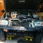
Revisiting this for clarification, hindsight, and new wisdom: The inner collar on the RH shaft is for the oil seal installed at the differential. FSM says to not reuse the collar, but I see no compelling reason to not reuse it unless it is excessively worn where it makes contact with the seal. This oil seal is the primary seal, so if there's gear oil leaking on the RH side, this is the culprit. The outer collar on the shaft is for retaining the bearing. This collar MUST be destroyed off with a chisel or similar means in order to replace the bearing and/or seal. Don't attempt to press the collar off...you will destroy the "extension tube retainer" plate that the outer grease seal fits into. The bearing and collar are no longer available from Nissan, but aftermarket kits having part numbers with "RW114R" should include both a bearing and collar (the seal is separate). This seal also does not stop gear oil, it's just for greasing the shaft that rotates in the retainer plate. You can apply your flavor of RTV on things if you'd like.
-
Your CV will have two snap ring grooves: inner and outer. The Warn hubs used the outer groove. For this style, you put the snap ring on the inner groove, then install the hub.
-
Great job and thanks for the photo sharing!
-
 Thanks! Yes, definitely a few W/D21 and even W/D22 compatibility (100% for their H233B).
 -
Twelve years of owning an R50, and almost 28 years owning and working on Nissan trucks (and cars, briefly)...and I'm just now getting around to putting together something like this. Still seems like people are trying to keep these trucks on the road, so hopefully this helps. This is a current matrix of maintenance and service parts for the R200A and H233B axles/differentials found in R50 Pathfinders and JR50 QX4. It covers all basic parts like seals and bearings, providing the current Nissan part number, superseded part numbers, quantity used, and a few suitable aftermarket part numbers. It also indicates which parts are No Longer Available ("NLA") from Nissan; they might still be available from international brokers and suppliers like Amayama.com and Partsouq.com. This list (particularly the aftermarket part numbers) is not comprehensive, but should be a good starting point; nearly all of the parts listed have a confirmed cross-reference to the OE part, some I've personally used. RockAuto's part number search DOES search across interchange numbers listed on parts; enter the OE part number without hyphens (i.e., "3818921G17"). There are definitely other parts that will work, especially more-affordable options; compare the specs of a listed part to other parts. It does not include any differential parts, LSD parts, or parts that would be needed to set up gears like shims and spacers...the majority of those parts are completely unavailable. The best option if wanting to change gears is to source a complete 3rd member or entire front differential from a donor vehicle, and service it using the parts from this matrix. Due to the nature of the high-pinion R200A we have, there are NO aftermarket gears available for it. Again, this is SPECIFICALLY for R50 trucks only. Other R200A front differentials (like those from W/D21, W/D22) do use some of these parts, but not all. The H233B data is for 33-spline only. Again, some parts do interchange, but some do not (mainly the inner seals and outer bearings which are sized smaller for 31-spline shafts). Keep in mind replacing many of these parts requires access to specialty tools, like pullers and a floor press, to disassemble and/or assemble components. Most of these parts cannot be bashed off, and some rental tools at your local auto parts store may be insufficient. A clamshell-style bearing puller like this works great for pulling pinion and carrier bearings. The matrix likely applies to foreign Terrano and Regulus models, too, but do your homework because you know Nissan did some really dumb things with these trucks. Part R200A (R50 Pathfinder ONLY) H233B (33-Spline ONLY) ! Qty OE Part # Supersedes NLA Aftermarket Part # ! Qty OE Part # Supersedes NLA Aftermarket Part # Pinion Nut 1 38216-U301A 38216-U3000 1 43262-50A0A 43262-50A02 Pinion Seal 1 38189-21G17 38189-21G15 38189-21G16 Y SKF: 15882 National: 710591 Timken: 2011S 1 38189-C7123 38189-C7021 38189-C7023 SKF: 16468 Schaeffler: SS2722 National: 710245 Timken: 710245 WJB/InMotion: WS710245 Outer Pinion Bearing 1 38120-1320A 38120-13201 Timken: 32306 WJB/InMotion: WT32306C SKF: BR32306 1 38120-1320A 38120-13201 Timken: 32306 WJB/InMotion: WT32306C SKF: BR32306 Inner Pinion Bearing 1 38120-61000 National: 32307 SKF: BR32307 Timken: 32307 1 38120-76500 38120-7650A National: 32308C SKF: BR32308 Outer Shaft Seal (LH) 1 38342-N3100 38342-P9000 SKF: 550231 Beck/Arnley: 0523506 Timken: 223542 National: 711070 A 2 43232-42G10 43232-42G00 National: 710176 Beck/Arnley: 0523492 SKF: 22120 Timken: 710176 Outer Shaft Seal (RH) B 1 40227-31G00 National: 710398 SKF: 19689 Schaeffler: SS3016 Axle Shaft Bearing (LH) Not Applicable 2 43210-0W000 SKF: GRW190 Mevotech: H516005 Beck/Arnley: 0514115 BCA: WE60346 National: 516005 Schaeffler: 101836 GMB: 7500024 Axle Shaft Bearing (RH) B 1 43215-H5000 43215-22500 43125-H5000 Y WJB/InMotion: WBRW114R Timken: RW114R National: RW114R Duralast: RW114R Axle Shaft Bearing Collar (RH) 1 43255-H1000 43255-18000 Y Not Applicable Inner Shaft Seal (LH) Not Applicable C 2 43252-0W000 Timken: 710479 National: 710479 Beck/Arnley: 0523727 SKF: 14782 Centric: 417.42011 Inner Shaft Seal (RH) 1 43252-H1000 SKF: 550232 Timken: 1181 Carrier Bearings 2 38440-N3111 National: 30209C Timken: 30209C BCA: NB30209C 2 38440-60000 Y National: KC11445Y SKF: KC11445Y Timken: KC11445Y WJB/InMotion: WTKC11445Y Differential Gasket D 1 38320-21W00 38440-N3110 38440-N3100 Y NONE - See Notes 1 38320-T3322 38320-T3321 38320-T3320AS 38320-T3320 O-Ring - Side Shaft Bolt (LH) 1 38223-21000 33125-Z5002 Not Applicable O-Ring - Outer Axle Tube Not Applicable C 2 43085-42G00 Beck/Arnley: 052-3568 SKF: 42G00 Fill Plug 1 00931-2121A 00931-21210 00931-21200 1 00931-2121A 00931-21210 00931-21200 Drain Plug 1 32103-U840A 32103-U8401 1 32103-U840A 32103-U8401 JPG version ! INSTALLATION NOTES A Axle shafts must be COMPLETELY disassembled (ABS tone ring, bearings, bearing cup, etc.) in order to replace the outer axle seals. This process requires a suitable tool and/or press. These seals are mainly grease-catchers for the bearings. However, if the inner seal is leaking gear oil, it likely has compromised the bearing grease. Axle shaft tear-down is recommended to regrease the wheel bearings and replace the seals. B Replace the RH outer shaft seal, outer bearing, and bearing collar together. The bearing shaft collar MUST be destroyed-off with a cold chisel BEFORE the bearing can be removed, and before the seal can be replaced. Attempting to pull the side shaft with the collar installed WILL destroy the flange plate (38232-01W00) and bolts. Ask me how I know. The "RW114R" kits all include a bearing and new bearing collar; the seal is sold separately. A slide hammer is needed to pull the shaft from the bearing, and a press is required to install the bearing and bearing collar on the shaft. C The axle shafts must be completely removed from the axle in order to replace the inner shaft seals and outer o-rings located at the ends of the axle tubes. This requires disconnecting the parking brake and hydraulic brake lines from the drums. The axle shafts will rest on seals, and potentially damage them, when the axles shafts are only partially pulled from the differential. FSM says to remove the ABS sensors from the axle tube to avoid damaging them when pulling the axle shafts. D The R50 Pathfinder uses a 9-bolt R200A differential only found in E50 and E51 platforms. All other R200A, R200, and C200 differentials found in other Nissan trucks and cars have 8-bolt covers. There are NO aftermarket gasket options for the 9-bolt differential.
-
70 ft-lbs is just to seat the bearing fully, not the final torque spec. Snug it up, rotate the hub, loosen the nut completely (do it twice if you're not sure it's seated). I like to also give the hub a few love taps with a dead blow when it's snugged up. After it's loose, "tighten" 4.3-13.0 inch pounds (same emphasis as Slartibartfast that it's about 1 foot pound max, not 13 nor 70 foot pounds). The nut is just barely against the bearing cone, and the lock washer and screw are what prevent it from backing out. Even with a short distance, it was probably extremely harsh on the bearings. They're probably fine, but personally I'd be pulling everything back apart, degreasing them, and visually inspecting them before putting it all back together. Or, just address the tightening issue and let'r ride.
-
SFDs retain stock suspension, steering, and front driveline geometries. They are intended to drop the subframe and all components a static distance; since everything's on the subframe, everything should be retained for the most part. There are some subtle nuances, like potentially still needing camber bolts, having to rotate the steering rack a little, and changes in the front driveshaft angle...but nothing that impacts daily drivability. As Slart explained it, it's basically a body lift, except for a subframe.
-
Agreed, the 2nd part appears to be some sort of NVH damper. It's not a transmission mount, that's for sure. If you buy from Amazon, you can search for the 1st p/n and it'll return a bunch generic options. Ebay, too. Anchor 9011 for $19: https://www.ebay.com/itm/297995046269. If you have a clunk when you change gears, the problem is more likely to be your motor mounts, specifically the driver's side. If your transmission mount has sheared or shows signs of shearing, I'd be certain at least one of your motor mounts has already given up the ghost. I changed mine out a few years ago on a whim, and the 2 pieces came out in 4.
-
RR sliders use 2" square tube and 1.5" round tube, 3/16" thickness. Using the QX4 mounts has worked out well. My buddy took the same approach with a universal set of sliders and they turned out great.
-
1997 Pathfinder 4x4 Rear Differential swap
hawairish replied to AR97Pathfinder's topic in 96-2004 R50 Pathfinders
Not limited to 00+. The trucks that had it were 2WD...but maybe some really old W/D21 4WD before 4-wheel ABS systems came into play. For sure, that setup has existed for a long time. My 98 2wd Frontier had it with the H190 axle, and now that I have an H233B in it, I used an older Hardbody diff to retain the system. Stated differently, it won't matter if the diff has it in your case. It won't get used, and you won't need to remove it. But the flange protrudes a little farther than the non-ABS version because it has more components to work it, but the bolt pattern is the same (I overlooked you said it was from a Frontier). You can't move your flange to housing because it won't clear the snout due to bolt holes that mount the sensor flange. The longer flange means you need to confirm that your driveshaft doesn't bottom out in the t-case when the rear suspension is fully compressed. Parts look like this: -
1997 Pathfinder 4x4 Rear Differential swap
hawairish replied to AR97Pathfinder's topic in 96-2004 R50 Pathfinders
The 2WD 3rd will physically fit all the same, but if the pinion flange is like how it used to be on trucks with the ABS sensor on the pinion snout, the flange will be about 3/4" longer than models with the ABS sensors at the drums. Though...I want to say some 2WDs (maybe the QX4?) had a CV-style driveshaft with a different bolt pattern. Pics would help confirm that. All R50s have 33-spline. The 31/33 split applies to Frontiers. Xterras were all 33-spline...you can use a 3rd from a 00+ Xterra or Frontier as well. Same HG46 ratio. -
You'll probably know it as "high pinion" (reverse cut) and "low pinion" (standard cut), much like the reference on Dana axles. The pinion line is either above or below the centerline of the ring gear. Rotation's all the same, but the teeth on the gears are cut in opposite directions. R200A from an W/D21 or W/D22: R50 R200A: In general, high pinion is best up front, and low pinion best in the rear due to gear mesh. But fck Nissan for making the R50 the only high-pinion R200A application. The short answer is they can't be (easily) swapped because they are mounted to the truck in completely different ways. The long answer:
-
I recognize that X from the Nissan SAS group. Welcome back. All R50s are 33-spline...but the problem with 4.9s is that there isn't a set that fits the front axle. R50s have reverse cut gears up front in the R200A; W/D22 are standard cut. You're limited to 4.6s, and hopefully that's what you already have.
-
A Lokka and 4.63 gears would go great with an air intake! (I'm your guy if you're interested!)
-
That's a head scratcher. Locking the hubs would cause more thing to spin. Unlocking the hubs would mean things aren't spinning, which makes it pretty hard for idle parts to cause vibrations.

