- Sign In Changes: You now need to sign in using the email address associated with your account, combined with your current password. Using your display name and password is no longer supported.
- If you are currently trying to register, are not receiving the validation email, and are using an Outlook, Hotmail or Yahoo domain email address, please change your email address to something other than those (or temporary email providers). These domains are known to have problems delivering emails from the community.
Leaderboard



Popular Content
Showing content with the highest reputation on 06/25/2019 in all areas
-
After getting the rear bumper finally ready for finishing, I decided that I was going to put some enamel colors onto the AZ flag and Nissan logos, and then bed lined around things. The enamel process was a bigger PITA than I had planned on (I hate painting), but I think the results turned out well*. (*=great considering my hatred of painting, despite not being pleased with the bedliner color.) I used tintable bed liner from Custom Shop on Amazon. The color is supposed to be Battleship Dark Gray, but I'd argue it is neither dark nor gray. I've complained to a few buddies that I don't like the color, but it does offer some degree of contrast that I was looking for. I still need to spray the sliders, and that will be a couple weeks out given my schedule, but I'll find out if that completes the "look". If I don't like it (and chances are that I won't), I'll probably pull everything back off for some spray paint (ugh) and get it closer to the dark gray I was hoping for. The bedliner product itself I'm pleased with; nice texture, hard, smooth, but provides grip without feeling rough. The Custom Shop stuff is the same as the U-Pol Raptor product. It was a mess spraying on the side of my house...I spent a day building a rack to hang all gear from, plus a few hours converting my HF easy-up canopy into a spray booth. Mostly successful, but I hated every minute of it. The front bumper got sprayed, too, and I finally got around to mounting the IPFs graciously donated to the cause by @Jax99. I have yet to wire them up, though...trying to find a decent switch for the left-hand panels, as the Carling rockers interfere with the dash a little. I thought I'd have some luck with a Toyota-sized aftermarket switch, but will go a different route.5 points
-
Finally got the rest of the lift In! KYB struts, ac springs, Nrc9447, bilstein 29" shocks. Sent from my SM-A520W using Tapatalk3 points
-
Finally got around to bedlining the carrier, along with the bumpers and such. Not a fan of the color and will probably re-spray them, but I like the texture and finish. All the brackets and other hardware just received a flat black enamel, but everything is bed lined. Color was supposed to be Battleship Dark Gray, but a little too blue/green for my liking. While I had everything apart, I also drilled holes into the carrier frame about 2" higher than where the tire mount body attaches. The reason is that I plan to make a 1" sq. tube frame that will be sandwiched between the frame and tire mount that serves two purposes: 1) the tube frame will give me mounting points for various things (think fold down tray, telescoping work light mount, jerry can, Hi-Lift jack, etc.), and 2) will also allow me to move the tire mount 2" up and 1" out for a little more clearance if (when) moving up a tire size. I've not constructed anything yet, but eventually.3 points
-
Sounds like you have a California-emissions truck. What I'd do is look for an ECU from a 90-95 donor with the same transmission and federal emissions. Those two wires on the EGR valve are for the EGR temp sensor (only found on California models only AFAIK), and if that's open or shorted, the computer will throw a code 35 (so no, jumping those won't help). You may be able to fool the computer with a resistor (the manual says the sensor should read about 85k ohms at 212°F), but I wouldn't be surprised if the ECU still threw code 32 (EGR function) afterwards. I'm not sure what all goes into setting code 32. The manual says to check the EGRC solenoid, vac lines, and the valve itself, so my best guess is that the ECU looks for temperature increase/decrease when the valve is opened/closed. Neither of mine have/had EGR temp sensors, so I doubt either would notice the absence of the EGR valve. I haven't done an EGR delete, though, so I can't say firsthand what works. How carbon-choked was the EGR valve when you removed it? Sounds like it might've been stuck open.2 points
-
2 points
-
I posted a teaser pic about this on the 'What did you do...' thread the other day, but time to shed more light on the project. Long story short, I'm making a winch bumper for myself, but that idea has evolved into making a builder kit for others to build their own custom bumper around. This is the progress... I'm still iterating through some small tweaks, but here are the general features: Uses an off-the-shelf winch channel, such as the Badlands (Harbor Freight) or GoPlus (Amazon)—inexpensive, universal, and the 36" width is perfect. Weld-together kit, but entirely bolt-on to truck; no cutting, no drilling. (Well...maybe a little trimming on the windshield washer bottle's plastic lower mount, but that's it so far.) 3/4" shackle mount (eyelet is 1-1/8" thick, or 3 layers of 3/8") Retains factory tow hooks Attachment plates for building any bumper style By itself, a winch mount Uses 3/8" steel for the bracket, and 3/16" for all attachment pieces. Uses all existing tow hook and bumper attachment points, plus three existing unthreaded chassis holes (blue piece in sketch is a nut-strip that inserts into the chassis); 18 total chassis attachment points using M10 and 1/2" hardware. 8" of vertical winch clearance. A side plate (red piece in sketch) provides mounting surfaces for the control box. Slotted channel on the main bracket that allows for attaching things. Currently, working on a bracket that allows the 00-04 OE fog lights to be attached. The bumper attachment plates (green and purple pieces) are what the rest of the bumper is built around. This allows the bumper to be completely removable. The upper plate's shape allows for using up to 1/4" plate on the top and front edges. Of course, the plate can be cut, notched, or bored to use tubing, but is basically intended to be a blank canvas. The lower plates (one inside, one outside the bracket) allow for additional mounting points. The inner plates, in particular, can be used to build a receiver tube attachment, or mounting a skid plate (00-04 models have a power steering return line that is exposed). I may incorporate use of carriage bolts (think single-tool tightening) and make it so the bumper can be rotated up for easy installation, or rotated down for service, winch access, even a step for engine bay access, by pivoting on the lowest attachment bolt. I'm also designing new skid plates, and once that's done, I will be getting everything plasma cut. Hoping to do all that very soon. I guess the real question at this point is if anyone would be interested in something like this? We obviously have very little aftermarket options between ARB (is this still even available?) and TAG (I can't stand the mounting setup). There's been a bit more chat about using XJ bumpers lately, but I'm not convinced that's a better option. While this isn't a complete bumper, I think this tackles the toughest problems about starting one. Down the line, I might make some weld-it-yourself kits that use this as the backbone. Even if you can't weld, this would grossly simplify the process for a local shop that could make you one. Questions and feedback welcome!1 point
-
Looking good - about time you painted all that steel. The IPFs are right where I ran my 130w KC Slimlight Driving Lights. That’s a great location for a forward driving light. Consider mounting floods at 30-45* angles in that protected lower lateral space (kind of where the fogs are stock). I had the Flood lens of the same 130w KC Slimlights in that location. I just barely overlapped the beam edges & it gave me about 200* of forward light stretching back to about the B pillars. I set it up for desert use when I was in AZ & have always been really happy with it.1 point
-
Yeah, I had a Federal vehicle.1 point
-
I did it on a 92 without problem. Did you plug the vacuum lines that ran to the EGR?1 point
-
You can try cutting down the threads on the end of the bolt and then cut a notch length wise in the bolt like a self tapping screw and try running it in. The threads are probably damaged a bit in the bracket and the notch might allow the bolt to clean them up. Otherwise best bet would be to pull the mount bracket and either run a tap through the hole or replace the bracket. I just went out and looked at mine to refresh my memory on how it all is and decided that was something else my 3" body lift makes easier. Also noticed that the mount I replaced along with the engine back in 03ish is looking like it is cracking at the top. Something else to deal with one of these days...1 point
-
Been doing things here and there when I can. Got it aligned finally, had to have the guy get at it 3 times but its whatever. I'm just gonna buy the 3 jigs here at some point and do them myself from now on. Began mocking up the air compressor today, bent a breather a bit so it will fit on the firewall. Now I need to make a harness. (yay...) Drove it to Yosemite to see how it is running, everything is fine but I'm gonna pull the thermostat this weekend and put some ATV around it so it doesnt leak which I think it might be. Was a bit low on water so only real reason why it would be since it is the only thing that's been messed with recently. Oh speaking of which I replaced that since it was bad. Making a jerry can holder. Almost done but going to finish it with my drill press rather than dicking around with a hand drill so that's held me up this weekend. Gotta lot to do this coming weekend. Going to run an inverter and hopefully figure out how I'm going to mount it to the headliner and make a harness for it, make the harness for the compressor and mount it, make back plates for the switches to me stamped at a later date, finish the jerry can holder and mount it to the tire carrier and mount the D rings in the cargo area along with clean it all out. Wish I could have worked on the carrier table, working away from home and having to devote a lot of time to my girlfriend when I am home on weekends is making it very hard to get a damn thing done especially with all the random house improvements I have been doing. Too much to do. Think I might ask one of my buddies if they are free to help me out and do some of the real simple crap. Just need a full 2 days or so of non stop go at it and I could get it all done myself but that isnt going to happen. I'll let you know what I get done1 point
-
Sneak peak fellas. Who can guess the color? Hint: New Toyota color released for 2018, Not Heritage Blue*- Correction Not Calvary Blue! Forgot that the fuel door latch was on the drivers door panel, so I had to drop it off so they could finish up, so got to snap these pics! Sent from my SM-J327P using Tapatalk1 point
-
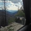
Sliders can’t come soon enough. Found another cool trail in South Idaho today1 point
-
I can't help it. I'm in love what can I say and I'm not afraid of showing it Sent from my SM-S737TL using Tapatalk1 point
-
We did a 72 mile off-road overnight trip. Sent from my iPhone using Tapatalk1 point
-
Stripped her down, cleaned up some of the trim pieces with a new coat of flat black and dropped the troutfinder off for her new paint job. Going to be prepping the flares for flat black too! Sent from my SM-J327P using Tapatalk1 point
-
I have some time tonight to poke around....thanks.1 point
-
The truck has definitely seen some use and abuse since my install, but not so much lately (and with the near 6" of lift, it's even more out of reach). Where the rear has typically been prone to the most damage is up around Sedona with all the rock-steps. If it weren't for my trailer hitch bearing the brunt of things, I'm not sure how the carrier may have faired. I'm thinking maybe I need some sort of hitch-mount slider or something to protect the tire, just in case.1 point
-
I’d start with the coolant temp sensor and the MAf sensor wiring. It is known to be problematic. I’ve worked on a ton of these trucks and I have never seen a failed fuel regulator before.1 point
-
Just some useful information I thought I'd share. Sometimes after replacing an old o2 sensor you will start getting CEL code 45 injector leak (sometimes other fuel related codes). Before you waste time and money fussing with your injectors you should reset the ECU with a 24 hour unplug. Because you may not really have a problem at all. This can be done but disconnecting the battery or by getting under the seat and carefully unscrewing and removing the ECU connector from the ECU. The latter preserves your clock and radio settings but is a little bit harder to get to. WHY? The FSM won't tell you this but Just resetting/Clearing codes won't work here because it does not clear the rest of the ECU memory. The ECU uses a trim feature to adjust your fuel based on o2 sensor feedback. The trims change as the o2 sensor ages and when a new sensor in place the trims may be too far off (usually because the old sensor was telling the ECU to run richer) so the ECU thinks there is an injector leaking. Doing a 24 hour unplug resets these trims so the ECU can establish a new baseline.1 point
-
On a side note to the original question, not positive if there is a write up however replacing injectors is easy. Take out the fuel pump fuse from the dash, turn the truck over and let it run till it does. Take off your gas cap and leave it off to decompress whatever else is left in the lines. Take off the intake manifold held down by like 5 or 6 Allen bolts (along with a lot of hoses, honestly this is the worst part). From here you can access all the injectors, they have a small c clip around the plug ins you need to take off (If I remember correctly that or it's just a clip) then just slip the connections off. If I'm remembering right there are 2 Phillip's screws holding down a plate for each injector you take off and that should be it. Then you just twist and walk the puppies out. Careful not to get any dust or dirt In the ports as you change them and leave the new injectors in the box until you are about to put in that one. I'd recommend going one by one just to reduce any chance of grime. Bolt everything back together and by on your way. If I've forgotten anything or left anything out my apologies however the process is very simple and straight forward.1 point
-
I thought he was working on it, I hadn't realized that it was done and running! Faster than stock is progress but I would never expect it to be "speedy".... it's a truck after all.1 point
-
Replacing the injectors will only get you clean injectors. it won't really "help" with emissions as that is controlled by the ECU getting signals from the O2 sensor, IACV , EGR and the MAF and adjusting fuel supply and timing in relation to what the parameters in the fuel map state is "correct". Best thing is to run new plugs, new wires, new cap, new rotor, new battery and everything with a perfect ground to bare metal; paying special attention to the MAF sensor wiring's additional ground. BARE metal is what you want. Now it'll pass smog, THEN you can throw down for new injectors! As far as modding the ECU, there was a guy on the west coast in BC who was suggesting that he was going to write up a different fuel map for the Path but that ended with an open ended thread and no more updates in the last three years. So unless you want to spring for a Jim Wolf ECU ( go for it!) there isn't much to be done to the ECU and little information exists here for any mods. You'll need to track down a tuning shop that works with Nissans... I suggest that Haltech in Austalia is a good place to start, they at least have Nissans that they work with on a regular basis.1 point
-
The RE4R01A transmission has a built-in temperature sensor. There ought to be a way to intercept that feedback from the wiring harness and connect it to a gauge without too much trouble.1 point