- Sign In Changes: You now need to sign in using the email address associated with your account, combined with your current password. Using your display name and password is no longer supported.
- If you are currently trying to register, are not receiving the validation email, and are using an Outlook, Hotmail or Yahoo domain email address, please change your email address to something other than those (or temporary email providers). These domains are known to have problems delivering emails from the community.

XPLORx4
-
Posts
2,583 -
Joined
-
Last visited
-
Days Won
47
Content Type
Profiles
Forums
Calendar
Everything posted by XPLORx4
-
Why did you have to weld two pieces in?
-
If the distributor won't rotate any further clockwise to get timing correct and you're still 4 degrees low, you should move it anti clockwise by one tooth to give you a more centered range of adjustment.
-
The distributor does sound like it was reinstalled one tooth off. The gear on the bottom of the distributor is helical, so the distributor shaft will rotate as you drop the distributor into place. I would note the position of the rotor, pull the distributor up to disengage the gear, rotate it slightly, then drop it back down so that the rotor is in a different position. A timing light will help determine if you're 15 BTDC.
-
I don't think any of the wires you've found on those boxes/relays on the driver's side feed the passenger tail lamp/turn signal. I could be mistaken, however. If you are looking for a definitive answer, you can use a multimeter or test light to see which connector or wire gets +12v when you activate the right turn signal.
-
To be honest, until I visited a junkyard for other parts and was fortunate enough to acquire the battery cable, I fully believed my solution was permanent. I’m sure whatever you came up with is fine.
-
Sent from my iPhone using Tapatalk
-
Are you referring to the cable that is actually 2 8Awg cables wrapped together which plug into the positive battery terminal and go into the fuse box and terminate at the BATT fuse? That is a part best sourced from a junkyard. If you can’t find one, you can do what I did. I bought a short length of positive 4awg cable, maybe 12 or 16 inches long, from either Batteries+Bulbs or an auto parts store. I ground off the sides of one end of the cable so it so it would fit on the lug in the fuse box, and bent and routed it back through the original hole in the fuse box to the battery. You’ll have to split the top and bottom of the fuse box apart to do this. Then, I unscrewed the 10mm bolt on the positive battery terminal and inserted the other end of the new cable onto the clamp, then reinstalled the bolt. I may have also ground down or flattened the edges of the cable to fit on the clamp. Last year, I found a cheap replacement part at a junkyard, so I swapped it back to OEM.
-
After reading about installation of an ammeter, I am dubious about its usefulness in a modern alternator-equipped vehicle. The Pathfinder's alternator is also capable of generating more than 60 amps, so that ammeter could get maxxed out if you actually use it. The most tell-tale sign of an electrical problem is often a voltmeter. We know that alternators generally output between 13.6 and 14.4 volts, and if the voltage is lower than that with the engine running, there's something wrong. That being said, if you intend to diagnose an electric drain when the engine is off because you frequently have a dead battery after sitting overnight, it's better to actually use a multimeter and insert its leads between the negative battery cable and the negative battery terminal to measure the current draw. A measurement above about 100 milliamps (0.1a) should be investigated.
-
https://www.fwmurphy.com/uploaded/documents/pdfs/00-02-0207.pdf
-
I use ATF in my TX10 part-time case.
-
Optionally, you could just unplug the horn in front of the radiator.
-
Open the driver's door and look at the lower corner of the door jamb on the body. You'll see a little rubber plunger. That's the door switch. When you push it in, it simulates the door being closed. The issue could be that the switch is not being depressed enough because of the door not being as snug to the body as it was when new.
-
As jjonez mentioned, it's likely one of the front door switches. Set the dome light to "DOOR" and close the doors. Gently push and pull the lower rear corner of each front door away from the jamb to see which door triggers the light. If the light goes on and off, then the button on the door switch isn't pressing deep enough to prevent it from connecting intermittently. You can remove the door switch from the body, being careful not to let the wiring harness fall into the body, then remove the rubber covering over the switch. Insert something like a pencil eraser into the bellows so that it rests between the button and the inside of the bellows. This will effectively lengthen the switch, causing it to depress more when the door is closed. Reinstall rubber covering onto switch, then reinstall switch in door jamb.
-
Maybe your Pathfinder is equipped with an aftermarket alarm? Does it just beep the horn or does it also make a siren sound?
-
Oh, got it. Yeah, I didn't read all of the whole thread. How's your camber with the 2" spacers and 3" SFD?
-
So, you've got about 5" of lift. When the front tires are off the ground, do the CV axles bind?
-
Did you make new adjustable upper and lower links? When I used adjustable upper mounts, I tried to tilt the axle rearward to align the pinion yoke with the driveshaft, but the panhard rod mount was angled too much and the springs were curved like this: ) because the axle mount was cocked rearward too much relative to the upper. I ended up having an adjustable panhard rod made, so that I could re-index the upper and lower mounts to account for their non-parallel orientation. Ultimately, I swapped back to the fixed-length upper links, and now with my double double-cardan driveshaft, at highway speeds, I get a slight growl that you could mistake for performance exhaust droning. I may need to remove the shaft and see if it needs rebalancing. I have even considered swapping back in the original driveshaft to troubleshoot a little more.
-
With that amount of coil spring lift in front, do you have any issues with the strut topping out over abrupt depressions in the roadway or when going over speed bumps? It seems that you may have very little down travel remaining in the strut.
-
How's it going with the rear axle progress?
-
I built a simple MDF box for a 10” sub and placed it on the left side of the cargo area. It’s easy to remove when I need the space. I have since replaced that box with a JL Audio stealthbox, and the one pictured is for sale if you’re interested. Polk Audio db105 driver. Sent from my iPad using Tapatalk
-
With a coil spring lift, the struts don’t bottom out, they “top out”, meaning they reach their maximum extension more easily. This is most noticeable over speed bumps or uneven road surfaces where the roadway ahead drops more than a couple inches. Of course, it happens while off-road also. The topping-out sound can be disconcerting to those who don’t know what it is, but it has never seemed to affect reliability or performance on my R50, and I’ve had the 2” springs for 20 years. While it’s true that a 2” subframe drop is probably ideal to avoid the risks associated with simple strut spacers as well as mitigate strut topping out concerns, a 2” subframe drop doesn’t make a whole lot of sense labor-wise. Simple 2” strut spacers (with or without subframe spacers) cause significant positive camber, which may or may not be wholly correctable using camber bolts. Keep in mind that an appropriately sized steering adapter will also be needed. If lifting 2” for the sole purpose of fitting 32” tires, I believe that the expense and time investment is not a good value. It might be cheaper and simpler to lift only 1 or 1.5” with OME springs, and trim the wheel wells or fender flares to fit 32’s. I suppose that it really depends on the reason why one wants to install 32” tires. For on-road use and looks only, just get strut spacers and camber bolts. For mild off-road use, get a mild coil spring lift and trim. For rugged off-road use, get 2” coil springs. Unlike a simple subframe lift, a spring lift raises the IFS/steering rack crossmember as well as provides wheel well clearance for larger tires. That provides more ground clearance under the front suspension. Just my opinion, based on nearly 200,000 miles and 22 years owning my R50 and wheeling it hard.
-
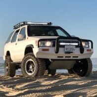
If you’re concerned about CV angles, don’t get spacers. Get springs. Spacers are cheaper, but they introduce the potential to overextend the CV joints when the front wheels are in the air. The photo I posted above shows my 97 LE with a 2” coil spring lift and 265/75R16 (32”) tires on 16x8 wheels. As I said previously, I ran 2” springs for almost 20 years, and ran 32” tires for almost 15. (The first few years of ownership, I ran 30” and 31” tires.) In case you’re wondering, about a year ago, I installed a 4” subframe drop in addition to the 2” springs in front. In the rear, I have 6” coil springs.
-
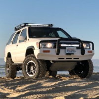
If you do any kind of off-roading, I would recommend 2” lift springs all the way around. A 2” subframe drop is extremely costly and complicated for the potential benefit. I ran a 2” coil spring lift for almost 20 years on my 97, and it worked great. Here’s an action shot. Sent from my iPad using Tapatalk
-
Before you assume the play in the rear axle is ring and pinion backlash and regear, consider that it could be due to worn side or spider gears in the diff. Nevertheless it might be less of a hassle to just swap out the whole third member than replace the gears. Sent from my iPad using Tapatalk
-
What size tires are you running? The LE came with 4.363 gears from the factory. You can confirm this if you look on the VIN placard on the firewall near the windshield wiper motor. You'll see HG43 (or HG46 for 4.636 gears). If you're running up to 31" tires, you can regear to 4.636. Regear to 4.875 for 32" tires. Regearing to 5.13 is better suited to 35" tires or larger. Install a speedometer recalibrator (http://yellr.com) after re-gearing to restore speedometer accuracy.