- Sign In Changes: You now need to sign in using the email address associated with your account, combined with your current password. Using your display name and password is no longer supported.
- If you are currently trying to register, are not receiving the validation email, and are using an Outlook, Hotmail or Yahoo domain email address, please change your email address to something other than those (or temporary email providers). These domains are known to have problems delivering emails from the community.


Bax03SE
-
Posts
376 -
Joined
-
Last visited
-
Days Won
36
Content Type
Profiles
Forums
Calendar
Everything posted by Bax03SE
-
Well, after giving the feedback/criticism some thought, I decided to pull the winch back off and add some reinforcement to the winch and fairlead mount. I’m sure it still isn’t the best design, but I do feel a lot better about this being able to spread the load out across more of the bumper. I was going for a minimalist design at first, but I agree it was a bit too minimalist.... Sent from my iPhone using Tapatalk
-
No worries at all on the criticism, I appreciate the feedback since this is my first venture into a winch set up. I’m not sure the thickness of the tube portion of the bumper, but the main cross frame is just a smidge under 1/4 steel. I didn’t measure it with a micrometer but I’d say it’s 15/64 or 7/32. I had a winch in mind from the beginning with this bumper, so I also boxed it in from behind before mounting it and added some triangular braces in a few places to tie a few parts of it together more. The brackets are all 15/64 steel and it ties into the truck with a total of 12 contact points. Of course I may be wrong still....but I feel pretty good about the strength of the bumper itself and the mounting points. I think you have a good point about the winch and fairlead brackets not being substantial enough so I think I’ll go back and add some more cross reinforcement between the two and also tie it back into the bumper more to spread out the load where it contacts the bumper.
-
That’s crazy how the spring popped out like that! Looks like it was a good trip.
-
With the welding all out of the way last night, I got the winch finished up this morning. I had to cut out the center section of the grill to clear the winch. It left a bit more open space above the winch than I liked and I wasn’t sure what i was going to do about it, but then I figured out my light bar would fill in the space just about perfect! I hadn’t quite figured out where I was going to put the light bar since It used to go where the winch is now, so that took care of two problems at once! Sent from my iPhone using Tapatalk
-
It’s a rock crawler bumper for a wrangler, modified to fit the R50.
-
I made good headway on getting the bumper ready to mount the winch tonight. Along with fabbing up a winch mount out of 1/4 inch steel, I also welded a section of 1/4 inch steel across the radiator support. It’s tied into the frame rails at each end as well as stitch welded to the radiator support across the front. I’ve heard stories of the rad support buckling a bit under winch loads, so I figured this would help beef up the stock thin sheet metal it is made up of. With this, plus the supports I welded on to the radiator support a couple years ago while doing some rust repair, my radiator support is significantly stronger than the stock piece ever was. Sent from my iPhone using Tapatalk
-
zakzackzachary's 2000 R50 new to PNW from AK
Bax03SE replied to zakzackzachary's topic in 96-2004 R50 Pathfinders
Looks awesome, I’m very jealous of those who can find the elusive spare tire carrier! I keep looking around here but none to be found yet. -
You’ll be fine with that load. I use mine for towing a lot and it’s very solid.
-
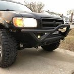
Picked up a new toy today!should make a nice addition to the bumper Sent from my iPhone using Tapatalk
-
Sent from my iPhone using Tapatalk
-
Finally got out for a day on some trails. It was nothing crazy, just a nice day cruising the forest roads in Wharton State Forest, part of the pine barrens in NJ. It was nice to get off paved roads for a day! Sent from my iPhone using Tapatalk
-
Success! I pulled the throttle body off after work, cleaned the crap out of it with b-12 chem tool (was careful not to move the throttle plate at all by hand). I also cleaned the maf while I was at it. Put it all back together and went through the relearn procedures, then got it fully warmed up and tested it several times shutting it off and back on and it idles great! It’s starting smoother now than it ever has. I didn’t realize the throttle body cleaning made such a difference on these things. Thanks for the input!
-
Sounds like exactly my issue. The electronic throttle bodies are weird since the idle air control valve is built in and not a separate unit. Now that I think about it, there was a time when it had improved a bit which was after I had changed the spark plugs and also did a half assed throttle body cleaning at the same time. I think I’m going to try a legit throttle body cleaning tonight and see what happens.
-
Okay so I’ve been living with this for a couple years..and am finally deciding to try again to figure it out. This is on a 2003 R50 with the electronic throttle body (drive by wire), auto trans. It will always start flawlessly when cold, but when hot it has a stumble for the first 2-3 seconds. If I just start it normally, it will start but then the idle will immediately dip way down to around 100-200 rpm. This only lasts about 2 seconds. If it doesn’t stall out, then the idle will pick up to normal range (about 750-850) and everything will be fine after that. Or, if I give it a little gas for the first couple of seconds after starting it to keep the idle from dipping down, then I can release the throttle and it will idle fine after that. Basically, I just have to get it through the first 2-3 seconds when the idle tries to drop, and after that all is good. It has absolutely zero drive-ability problems after that. I’ve performed the throttle position and idle air relearn procedures several times, and that doesn’t help. There are no trouble codes. Again this only happens on a hot start. I’ve gotten used to just blipping the throttle a little every time I start it, but I’d like to finally figure out what’s actually going on. If anyone else with the drive by wire system has experienced this I welcome the input. thanks!
-
I think this is what you’re referring to? If so the dimensions from hole to hole are approximately 22.25 inches, but it seems to vary slightly so it’s best to measure your truck. Its a simple mod, but can make a big difference especially if you do a sfd it adds protection against side to side twisting at the rear subframe mounting points.
-
Try swapping that wheel with a front and see if the wiggle follows the wheel or stays with the axle? That will at least tell you if it is a wheel/tire balance issue or something on the truck.
-
Figured I’d update this to include my current set up. Currently running 9449’s in back with a custom spring perch bolted on top of the stock perch for an extra 1.5 inches of lift. Ground to fender lip measurements are with 285/75/16 tires. Front measurement: Sent from my iPhone using Tapatalk
-
6" SFD with 6" lift build questions
Bax03SE replied to mandersen8's topic in 96-2004 R50 Pathfinders
Just to add a little justification for the cost, even building your own kit isn’t cheap. I just added up what it would cost me to replicate everything on my truck as it currently sits, and it’s right around $600 that I have in it. That not only includes the material to fabricate the sfd components, but also the front and rear HD springs, extended shocks, limit straps, etc.. Once you factor in the labor time to fabricate the kit, and the fact that there needs to be enough profit to make it worth your while, there is a good reason that it isn’t cheap to buy a good pre-made sfd kit. If you’re not trying to make a profit, have the means, and just want to make a kit for your personal rig, then the DIY approach definitely saves some money. This also makes a good argument for waiting for the upcoming “pines to spines” kit. As I understand it, they are making the components modular, so if budget is a concern you can start with getting the parts for a mild lift, and then “grow into” bigger lifts later on by adding onto the basic kit. Correct me if I’m wrong on that.... -
Looks great! I’ve heard a lot of good things about those tires, let us know what you think of them. I’m a long way off from needing tires but will strongly consider those when it’s time.
-
When I put on the tube bumper, I picked up some led cube lights that I wired in place of the stock fog lights. They were about $50 at Autozone and put out a surprising amount of light. Sent from my iPhone using Tapatalk
-
Shoot, I checked your profile and it looks like you have a pre facelift. If it was a post face lift, I have a full bumper cover with fog lights in storage above my garage I was going to offer to send you whatever you need.
-
This is an old pic so it doesn’t show the current height of the truck, but the stance is the same. This is with 16x8 rims with 4.26 inch backspacing, and a 1.5 inch wheel spacer, so effectively 16x8 with 2.75 inch total backspacing. Sent from my iPhone using Tapatalk
-
I personally like the wide stance look, but it definitely results in a lot of junk getting thrown down the side of the truck. I have a pretty wide stance past the fenders and I’ve just kind of gotten used to always looking like I just drove through a mud pit even if I just went through a puddle at wal mart! Lol.
-
I actually did the exact same thing and went with a 3 inch sfd just to get the extra inch of ground clearance under the front sub frame assembly. This is a slight compromise as my cv angles aren’t quite back to 100% stock, but they’re still within the safe range of travel as described by what you get with just a spring lift. Basically, I put in enough of a sfd to offset the strut spacer portion of the lift and keep maximum droop within a safe range.
-
One thing I generally love about this forum compared to other car forums, is people genuinely talk to each other with respect and aren’t always trying to one up each other. That being said, let’s all take a deep breath and a step back on this one....lol. I think everyone is trying to help and a lot is just getting lost in translation. Here’s what I know from my personal experience with several different set ups. Spacer lifts and spring lifts both increase the static angle the same amount, thus effecting CV boot wear and camber the same when at normal ride height. The difference is in the maximum angle at full suspension travel (full droop). The stock R50 struts have about 3 inches of down travel before they max out, and anywhere within that 3 inch range the CV is generally safe from binding. With a spring lift, you’re only working within that 3 inch range of travel. A 2 inch lift will use up 2 inches of down travel, leaving only 1 inch left (hence some people experience top out). But the CV won’t bind up and Grenade itself at full droop because it is still at the same maximum angle as stock. Now say you have a 2 inch spacer lift on top of the stock strut and spring assembly. At static ride height, everything is at the same angle as it would be with a 2 inch coil spring lift. But, in this case you still have the full 3 inches of strut travel available. So if you unload the front suspension and let it hang at full droop, you will now have a full 5 inches of downward travel and the CV will be beyond it’s safe limit of travel. If this happens while the front axles are spinning the CV will bind up and something will most likely break. That is why people say spring lifts are safer, because they don’t let the CV travel past it’s stock limits for downward travel. With spacers, 2 inches is generally the max you can go and “probably” not break anything. If you put in anything larger than a 2 inch spacer without a sfd then probably not becomes definitely will break something. Now SFD’s really come into play when you want to go past 2-2.5 inches of lift. Dropping the sub frame let’s you go beyond 2 inches while still keeping the CV’s at a safe angle and also keeps camber within spec by bringing down the lower control arm mounting point. Most people with a SFD achieve the lift through a combination of both strut spacers and lift springs, then drop the sub frame whatever amount is needed to bring all the angles back into a safe range. So if you have a total lift of 4 inches with both spacers and springs, then you use a 4 inch spacer to bring the sub frame down to match it. Here are a couple pictures of my front end that were taken while in the process of doing the sfd. The first is with full lift in place (combination of 2 inch spacers and 2.5 inch spring lift) but without the sfd. You can see the CV and lower control arm angles are all out of whack. Then with the sfd in place everything is back to lining up much more reasonably. Hope this all helps! Sent from my iPhone using Tapatalk