- Sign In Changes: You now need to sign in using the email address associated with your account, combined with your current password. Using your display name and password is no longer supported.
- If you are currently trying to register, are not receiving the validation email, and are using an Outlook, Hotmail or Yahoo domain email address, please change your email address to something other than those (or temporary email providers). These domains are known to have problems delivering emails from the community.
Leaderboard



Popular Content
Showing content with the highest reputation on 07/29/2018 in Posts
-
I might be making a limited run of adjustable or static arms if folks are interested. Just about done with this set for FerrariOwner123. 1.75" OD/0.180" wall Chromoly tube with 1.25x12 rod end adapters. Welded and turned. The post welding machine work isn't necessary but I prefer the aesthetic. Hes supplying his own rod ends but I can fabricate/supply those too, if needed.3 points
-
They can be set to stock lengths or extended for lift. The threaded rod ends are adjustable.1 point
-
I understand and agree with what your saying as people on this forum are normally pretty mellow and not looking to cause problems, but I would also guess that you probably don't go around posting your address all over the web either. You are of course free to do so, we just don't require or directly recommend it here. As for the off chance someone grabs the negative attention of a nut job, why make it any easier for them? Besides, I think that it's also fair to say that there are a number of them out there without the ability or patience to track someone down to an exact location. There are other, less paranoid, reasons as well. I personally was tracked down once via the original NPORA website. It was years ago, before I was part of the staff, before the current website and before the Member Map existed, but nonetheless it happened. Almost 10 years ago when we rolled out the new NPORA website the info that allowed that to happen was changed, for good or bad. In that case I was contacted via email by family I had not heard from in years and in that instance it was welcomed. However, today I have other family which I would prefer that they not just show up on my doorstep unannounced, if I put a pin on my house that could just happen. But again, placing it at your doorstep, city center or not at all is the choice of each NPORA Member.1 point
-
Thanks RainGoat. Will do. Panhard bars are definitely an option as well.1 point
-
You sure do pretty work & your commitment to quality work is only matched by hawairish. I kinda wish I didn’t already have those Terry Morgan ones. BTW, check with XPLORx4 as he had inquired after my adjustable panhard rod a couple months ago-probably long enough he’s already gone another route.1 point
-
Sold it. I tried to impress on the buyer the value of the forum, so maybe he will get on here and the pathy will live on.1 point
-
#VG34E1 point
-
1 point
-
1 point
-
1 point
-
test driving my truck after my engine swap. VG34e1 point
-
After fixing the air/fuel mixture problem by swapping the whole throttle body that was off the old engine (vacuum was ok, injectors, maf and tps too... perhaps there was some dirt clogging some duct or some vacuum valve sticking closed or open, I don't know), I performed a compression test. Values 1 to 4 cylinders are 155 - 150 - 150 - 155 psi with COLD engine (specs are 131 min and 173 max with HOT engine, so I should be on the high side); squirting some oil inside the chambers made me gain an additional 20ish psi per cylinder. I think this is ok for a 30 y. o. junkyard engine. The engine pulls strong and sounds good; only when going on LPG is not perfect yet (as said elsewhere, this car has an additional LPG fuel system fitted by the previous owner, with a 58lt LPG additional tank). Having zero experience with LPG fuel systems, I still haven't figured out what's the problem, but it shouldn't be anything major, Also, a new window regulator has been installed (being the steel wire of old one messed up) ... and a new rear window switch1 point
-
Sorry, what I meant to say was that I was considering supporting separate brackets, one for higher channel and receiver (for which I would also provide a kit), another for a lower channel without. Other ideas have also crossed my mind. Main takeaway at this point is that there will be options, including custom ones. Since TownDawg plans to use part of his XJ bumper for his build, I've got an offer out to him to customize the brackets to his liking. Fact is, he's already a fabrication pro at that stuff (whether he admits it or not). Since we have the same CNC routing equipment, we'll be able to collaborate on the design pretty easily I think. As long as he can wait a couple more months for a finished piece! But generally speaking, I'm hoping this project opens doors for other projects...you know, like a bolt-on SAS kit or something...1 point
-
Here's a daylight shot: One day, I'll actually start that rear bumper, giving me a better excuse to pull everything down and get it coated! We finally got some rain the other day...prior to that, it was fairly rust free. On the plus side, I finally started v2 redesigns this week on the bracket. I'm at a minor blockage rethinking where to put the shackle mounts due to other modifications, though. I'm currently planning to move them closer to the OE tow loops, about where the lowest bolt is in the pic. That would provide the necessary space for mounting a crossbar/receiver under the winch channel. I'm also playing with the idea of lowering the channel altogether, for those not wanting to find an alternate control box mounting position like I did...but it would lose the option for a receiver. I know this build has slow going, but we will get there... Not yet. The original plan was to have a batch done by my local steel shop, but we're fast approaching the time when I'll be able to cut these in my garage for less. Equipment arrives late July, hoping to be on my feet early August. That gives me time to make my design changes, set up shop, get material costs, get a new head-count on interest, and start cutting stuff. Exciting days to come!1 point
-
How did i miss this thread? Such amazing work as per usual -Kyle1 point
-
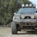
I'm long overdue on a reply here! Unfortunately, I haven't been able to touch this project for several weeks due to all sorts of stuff, but this week is looking a little promising. Right now, I'm about 85% done with the bumper: I've been driving it around like this for a while, and well...it hasn't rattled off the truck, so I must be doing something right. What remains are mounting the winch solenoid box somewhere, and putting some sort of coating on. The former issue has been a pain...the control box is somewhat large and obnoxious, so I'll likely end up using my CNC router to create a mounting plate from 1/4" ABS sheet and mounting the box vertically in front of the radiator behind the grille, plus some other re-wiring to relocate the remote control plug. More work than I was hoping to do, but whatever. For the latter, I'm leaning towards using Monstaliner and one of their tintable kits, probably just their dark gray (not a fan of black). I'd love to go with an orange color (for bumper, sliders, tire carrier, and rear bumper when done), but I'm not really flashy like that...and there's a small premium on most colors. Of course, that 85% excludes a bunch of other smaller tasks, like blacking out the washer fluid reservoir and deleting the pre-airbox squid. I'm also trying to figure out lighting; might just go with 4 cheapo LED pods inside the angular openings. I've not welded up the skids, but I did make the necessary bends: I achieved my goal of making this a slide-on/off process. Just loosen the six bolts (4 under the radiator support and 2 under the crossmember) maybe 3/4" and slide forward. I may actually weld the two skids together, though that wasn't the original plan, but it'll work fine like that. Reason for wanting two pieces was to have 3/8" of steel plate under the support. With my existing mid-skid plate, I've also got additional layers under the cross member. I may also add some side wings for a little extra covering of. The ribs on the backside of the plate might be a little too close to the sway bar on articulation, but I may just test it out as originally planned. It may only make contact if my front end bottoms out, but when I replace my current OME MDs with HDs soon, that'll rotate the bar upward for more clearance. I can move the skids forward a little to add some clearance, too. .... I've been really slow on making progress towards getting the next set of brackets cut up, for several reasons. But, I've not lost sight of the project. My main concern is seeing a real-world application (mine) and making any corrections or improvements. The other thing is still avoid a repeat of the file snafus from the first set...too much rework on files. I intend to re-CAD my original drawings in another application, and that's just a matter of time becoming familiar with the application. The same application will be use when I get my CNC plasma table...oh yeah, I hinted at it previously, but it's official: I bought a CNC plasma table. I won't see it until June, though, and I'll need all the time until then to get a plasma cutter, air compressor, and electrical drops in the garage. I would like to have the 2nd set of brackets cut by the local shop still, just to not stall getting these out there. There will be a v2 design with the following changes, and I'm open to questions, concerns, and suggestions: Shackle mount depth: the shackle hole will move forward and protrude beyond the face of the bumper. I like the recessed location in general, but it presented some issues when trying to avoid blocking access. Hi-lift flat: one thing I wish I had incorporated was a simple flat spot for the tongue of a Hi-Lift to fit under. This might not be useful for all builds, but would be easy to incorporate. Shackle mount width and/or orientation: The current width is 1-1/8" (3x 3/8"), ideal for a 3/4" shackle. I don't want to change the width, per se, but the layered approach (pieces on each side of the main bracket) created some limitations when determining how to mount the bumper to the brackets. I may reduce the layer to two, giving 3/4" (2x 3/8") of shackle width, which actually seems pretty standard on other bumpers. Fewer attachment plates: the current design uses 3 separate plates for attaching a bumper face to the main brackets. I found this to be a pain, in terms of aligning everything and accounting for metal twisting from welding. The next design will have two plates (one per bracket) only. I will probably have a separate set of places specifically for creating a receiver tube attachment. General main bracket: couple small changes here and there regarding cuts, shape, etc. Hopefully more to follow this week...1 point
-
Sorry, Saturn, time hasn't been on my side since my last post. But, am still working on clean-up. I'm also wanting to wait just a little longer until I can get more of my bumper going so that I can get a better idea on the changes. Progress there has been slow, too, but it's coming together. I should clarify that mine likely won't be a true snorkel by any means, but rather a duct re-route somewhere under the fender. There are some universal flex ducts (and not the stuff for clothes dryers) that I was thinking about, but I've not looking into routing options quite yet. I just need something to replace the wonky pre-airbox-airbox. Not necessarily this, but like this: https://www.amazon.com/dp/B01J3JGDM2 I remember seeing this approach and thought it was clever. I'd rather not modify the airbox if I can avoid it, but my goal is less for water intrusion and more for getting rid of that ugly pre-box. It's something I can look into! ... As a small update, things are going slowly. The core bumper is together, still need to tack up the tubes under the channel and do the wings. I toasted my metal-cutting saw blade the other day, so I'm dragging my feet to do the remaining compound cuts I need before I break down and buy either another blade or proper chopsaw. Not sure what it is, but this .120" tube has been exceptionally brutal to both my saw blade and the cut-off wheels I've got, noting that the same blade has cut through .250" steel without issue before. I guess that's a good sign for the bumper, though. Haven't really paused long enough to take more pics than this, unfortunately. But since this pic was taken, I've filled in more welds and smoothed up the tube ends under the fender. Made no progress over the weekend due to being out of town.1 point
-
The TBI trucks don't adjust base timing like the MPFI trucks do. So on his (TBI) there's some benefit to bumping the timing to 15° It's old school tried and true. An MPFI truck wouldn't see any benefit.1 point
-
Yup, also common on the Xterra.1 point
-
Mine failed a while back, it was the camshaft angle sensor that is inside the distributor that stopped working properly. The distributor looked to be in VERY good condition given its age, but that sensor flaked out. Others have reported coil pack breakdown and failed bearings to be ways it can also fail.1 point
-
Yes pretty common nowadays. Repeat failures are typical of cheap replacement parts.1 point