

hawairish
-
Posts
2,684 -
Joined
-
Last visited
-
Days Won
318
Content Type
Profiles
Forums
Calendar
Posts posted by hawairish
-
-
Have you talked to Rob Lacy (Alkorahil) about getting the parts? This sounds right up his alley...
Been thinking about it. Been to the website, too. The prices between them and my norms are about the same, but I usually go with Courtesy because of the Nico discount, which has basically covered shipping ($40 in this case). Now, if there's an NPORA discount...
CP has been good about things, but they dropped the ball this time. We had some delays sorting out numbers/availability for these discs, which took too long to sort out. Found out this morning that they've been holding the older for a back-order item that they optioned to me to split off, and I took the option. SFD install: delayed. Lokka install: delayed. LSD rebuild: delayed.
-
Well, worth a shot, I guess. Did you try wiggling any of the harnesses or wires while running? Wouldn't remove any while truck is ON. Are all the screws on the back snug?
As for the other wires...well, everywhere. The FSM should spell out specifically what wires to look for (color, pin position, connector type), how to test, and acceptable range (voltage, resistance, etc.).
If I were troubleshooting this, I'd be working a multimeter on the back of the gauge cluster and watching the voltage during revs (assuming the tach readout is voltage-based, which I'm sure it is). I'd first probe on the tach itself; If the readout increases with engine RPMs but the needle jumps or flatlines, then it's probably the gauge itself. Then, start working away from it: on the circuit board near tach, on the circuit board near the harness, and then on the harness. Keep working away from the tach. I believe the next point is the distributor (this is where I wired in a tachometer on my 1998 Frontier); the gauge cluster is between the distributor and ECU and I don't think there'd be any more connectors, except at the distributor, IIRC.
You can also try putting the multimeter in Ohm mode and check simple resistance between the points I mentioned above (may need to wiggle things...check for continuity first, then wiggle something to see if drops).
-
Word. So was tightening up your LSD because the stock one wasn't enough? That was the original conclusion I was hoping to understand (from anyone), since it would've played into what diffs, discs, and what nots to look for and purchase.
Not really relevant now, since Nissan didn't have as many discs as I originally wanted. I scaled back to what was available (yet the dealership apparently still has their thumbs up their a's, and all my projects are postponed...) The nice part is that I can bench test everything before taking apart the truck, but it just gives me a number and not a "feel".
-
Shouldn't take more than a Phillips to pull the gauge cluster, I think...at least that's how it is on my 04. Two screws for the bezel (slide your hand palm up above the cluster and you should feel the holes), and 4 for the cluster, in my case. Was similar for my Frontier, but I had to remove some lower plastic to see the lower screws.
I had issues with my Frontier cluster long ago...the printed circuit board ('sheet') had started to crack near the connectors...was causing the illumination to sometimes turn off half the bulbs (hitting the dash helped), but also caused the speedo needle to go flat (which interrupted the speed sensor signal to the ECU and threw some errors). Bought a replacement board from Nissan and everything fixed.
The new clusters use a rigid circuit board, so it's not an issue. But judging by the pictures in this auction, it uses the flexible circuit board. The white parts on the back are where the connectors go. Mine were cracked near these openings where the board flexes to make contact with the connect. The cracks were tiny, so look carefully.
-
Yep, I get the extra disc part; you added a disc to each side, and each is essentially half-height. I wouldn't be able to tell if you were in or out of OE spec without knowing your initial stack height (which is what I'd really like to know). In my case, I could do what you've done and still be in spec.
The two LSDs I broke down had very low stack heights, and consequently low break-aways. I was surprised to see that 150% more friction surface and .1mm (.2mm total) only produced another 25 ft-lbs. The "better" LSD has the same disc:plate setup as the WD21, but produces 25% of the OE WD21. The standard size part was 1.5mm, and assuming the stack used all standard sizes, that'd only be 19.5mm (mine are 19.3mm and 19.4mm; both will be 19.6mm). That all said, the WD21 must've had some 1.6mm to go above 19.5mm. If you went over with your shims, you must've had at least that. Do you recall having any 1.6mm discs/plates in those stacks?
-
B: Those OD/ID numbers pretty much killed it, at least for using an LSD carrier and side gears. The ID is just a little smaller than the OD on the side gears (sorry, don't have my measurements handy to give exact numbers). Even if the numbers were better, the cut on the teeth surely wouldn't mesh right:
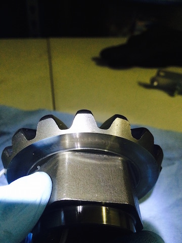
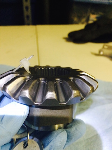
Getting somewhat decent measurements was tough with all the angles and round edges/faces.
I'm not surprised by the results though. In the pics I've seen of the 2-piece open carriers and 2-piece LSD carriers, the LSD "center" is noticeably smaller (there's a gap between the center and the ID of the ring gear). Haven't pulled the open carrier yet, but I think I've seen the side gears look very similar, which makes this a no-go.
MY1PATH: Do you remember if your stacks were still within OE spec after machining them down? I'd still love to know what the original stack height was to pull those OE torque numbers.
-
Yeah, they can be welded. Short of pulling the engine (and probably not even necessary then), there's no compelling reason to pull the subframe down...except for an SFD!
So, sounds like this hardware dilemma you're in might ripple elsewhere. Probably best that I give you more heads-up so you can assess the big picture. That said, let's talk hardware...
I just wrote this up: http://www.nissanpathfinders.net/forum/topic/40356-pre-installation-check-up-before-getting-an-sfd/
Long story short: I wouldn't worry about the front subframe bolts. That has an easy workaround. If the rear bolts spin, you might be in trouble. But, I thought of something that might be better than what Patqx4 and I noted previously that doesn't require major invasive surgery to the unibody.
-
Rather than clutter up CDN_S4's build thread with info that might be useful for others, I thought I'd regurgitate some knowledge that everyone considering an SFD should be aware of before going forward with it. In CDN_S4's case, he's dealing with some rust issues that make removing hardware difficult, but for every problem: a solution.
Before diving into things, you'll want to check out these areas so that you can better assess how to install an SFD. I hope to have thorough installation instructions in the near future, though there are some good existing write-ups (most useful so far: http://www.nissanpathfinders.net/forum/topic/31584-my-pathy-project-lifting/)
That said, let's go...
You'll need to remove/loosen bolts in these locations:
front subframe
rear subframe
steering link
steering rack
motor mount
CV/axle/front driveshaftstrut
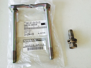
Front subframe: The front subframe "bolts" are actually two bolt assemblies, and they can be replaced. They're 12mm x 1.25 x 150mm bolts affixed to a bracket. You can get new ones from Nissan (54418-0W00A; OE flange nut is 54588-0W00A, or OE equivalent is Dorman 433-512...Nis), or just replace them with (4) 1/2"-20 x 6" bolts and matching hardware. I tested this with 8" bolts when test-fitting the 1.5" spacers. Can't go wrong with thick SAE washers, but the OE bolt doesn't even have anything washer-like on the assembly. But, if you go with separate bolts, you may need a helper to keep a wrench on the bolt head...the OE assembly prevents the bolt from spinning. They can obviously be welded in, too.
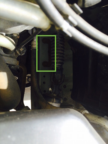
Left: front EO subframe bolt assembly; Right: rear OE subframe bolt. Both shown in the orientation they are installed in the truck (fronts down, rears up)
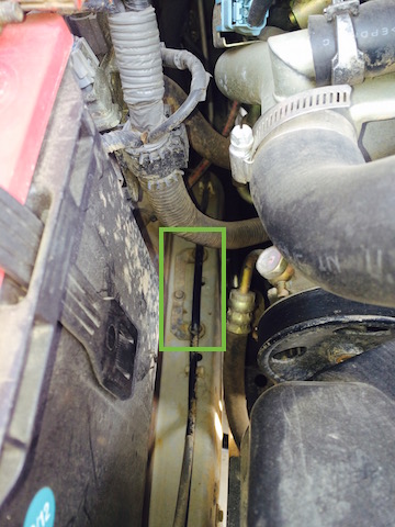
These assemblies are located in the engine compartment on the unibody "rail" where it opens up for the engine. The passenger side is tougher to get to because of a rigid line that runs directly over it. The drivers side requires disconnecting the steering shaft. Both are held in by an 8mm bolt. In my case, the bolts were in good shape and were re-used, but the flange nuts should be replaced when removed.
Passenger side:
Drivers side:
Rear subframe: These bolts are 14mm x 1.5 x 45mm (p/n 54459-0W01A). It's only threaded to 35mm. If you can re-use the threaded holes, you'll need that bolt size. If these bolts are spinning, that will be a problem.
Steering link: You'll need to loosen the upper and lower bolts at the ends, and completely remove the middle bolt (otherwise it can't collapse enough to remove the link...ask me about the 15 mins it took to remove the link).
Steering Rack: You will need to rotate your steering rack. There are two 22mm bolts, and they're on tight. There's also a bracket that connects a rigid line to the crossmember, and another bracket on the reservoir hose that connects to the unibody. Both brackets will need to be disconnected.
Motor mount: each motor mount has two integrated 10mm x 1.25 studs and uses flange nuts (08918-3401A). The nuts will have to be removed without damaging the motor mount, and are really only accessible after pulling down the axle.
CV/axle/front driveshaft: You've got the 12 CV bolts (6 per side), then 8 larger bolts (4 per side, 54710DA in the diagram, 54726-0W005) that connect the axle housing to mounting brackets. I don't have measurements on these bolts, but I expect they are 10mm x 1.25 (CV) and 14mm x 1.5 (axle). The front driveshaft will need to be disconnected; Nissan recommends replacing the 4 bolts and nuts when removed (37120-0P00A bolt, 37171-7S00A nut; I recommend OE parts because part of the driveshaft flange prevents the bolts from spinning, just need a wrench on the nut)

Strut: Since the struts will likely need to be removed if you're adding spacers or springs, you'll need to remove the upper strut mount (strut tower) hardware from inside the engine bay, and the lower bolts connecting to the spindle. The strut mount bolts, I believe, are 10mm x 1.25, but I'm not sure (they're affixed to the mounting plate, 54322 in the diagram), but it's all somewhat irrelevant. If you're adding spacers, you'll need to modify the mounting plate to use longer bolts. Mine were replaced some time ago, and the holes have been enlarged to accept 12mm or 1/2" hardware
The lower strut bolts are 14mm. If you're not using offset strut spacers (like those included in the KrF kit), then you might need 1 or 2 sets of 14mm camber bolts (set = 2 bolts), easily found on eBay.

-
 5
5
-
-
I have seen people add the tire swinger from older models and i happen to have one from my old 96. What would i need to do to reenforce the panel?
I hope to have that answer very soon. My inclination is nothing, despite a lot of other threads. Every has said there's reinforcement but I've never seen any definitive proof. It might as well be a miniature Bigfoot that holds everything together. (There was a bracket for the WD21, though.)
After diving through various p/ns and diagram, the part numbers only suggest the quarter panels differed between having holes or not, and having fender flares or not. There are no parts diagram that show any substructures or additional hardware for the tire carrier. Perhaps the panel is reinforced, but a video I took last weekend doesn't indicate any significant sound difference.
I'm hoping to test fit the carrier tonight.
-
But isn't this shimmy relatively new? Did it start before or after your recent trip? Sorry if I missed it in a previous post.
I agree with the mechanic's assessment to get the SFD on (see below). I personally think it's just because of the angle of your tie rods. If your tires are still visibly toed, your TREs must be at/near max length (and consequently a higher angle).
Here's how I think about it...what's more stable in terms of resisting lateral flex on the steering system?
(In very crude form, pretend the "/", "\", and "—" represent the TREs...)
1: [wheel] / [steering rack] \ [wheel]
2: [wheel] — [steering rack] — [wheel]
The more level the TREs, the better resistance, right? Not saying the TREs are bent/bending, but at an angle, there's just less ability for it to resist left-right motion. SFD is the answer.
I had a really bad shimmy when I got my truck. Got it aligned, and got the tires rebalanced...twice, actually. Rotated tires. No matter what I did, always happened at the same speed range. Kept thinking it was the Duratracs, and just learned to live with it and avoid the freeway. Put the SFD on, no shimmy...and that was without an alignment.
Obviously, you're in a dilemma to get that SFD on. Patqx4's suggestion is exactly how I'd approach it, and I don't think you'd need anything special except someone to maybe tack in a backing plate with a nut welded on, and to weld a patch over the access hole when done. You could use a drill-attached hole-saw bit to get easy access. And this could all be done separately from the SFD install. Doubt it'd take maybe more than a couple hours.
I didn't see an answer to which subframe bolts you're having problems with. Is it the rears?
-
1
-
-
That sucks, man. Which bolts are rusted, seized, or spinning? I'm assuming it's only the rear subframe bolts.
-
Excelente. And good luck getting all the stuff you need!
-
I was under the impression that the ignition switch was either riveted to the column, or used security bolts where the head shears off after fastening. Maybe just a security bit? Obviously, these things are meant to deter theft, so I can't imagine the process of replacing parts—whether the guts or the whole assembly—to be simple.
Almost seems like you'd save yourself some trouble by just buying the whole steering column...
If the cable I mentioned does exist, it should terminate near the ignition switch, I'd think. You could probably trick it there.
One parting thought...you didn't say whether you had an MT or AT, but the donor is an AT. If you have an MT and have the push button like what RedPath88 posted, something tells me you shouldn't get this ignition switch. (Unless you think you can just get the tumbler assembly and install it in your existing column). The whole point of both ignition lock types is to prevent the key from turning to the Lock position before the key can be removed. This is likely to prevent the steering column from locking while driving. I guess just make sure you're not defeating that system, right?
-
No sweat, B. In fact, let me post up a pic of the side gears and some basic dimensions first, then you can decide if it's even worth your time.
I've got two LSDs fully disassembled and sitting in a box now (all marked and bagged, of course). It's been an interesting project, but going a lot slower than I'd hope due to availability of Nissan parts. The friction discs are holding up the show. I switched focus to the pair of R200s, and installed a Lokka in one. Just waiting on new seals and gaskets to call the first one done, before doing it all again on the other.
The 2nd LSD has the "ideal" ratio I've been talking about in terms of friction discs. It's spec'd for 65-80ft-lbs, and came in at 68. Its stacks are only 0.1mm thicker than the 1st LSD, which does help correlate some numbers for me. I had to change my order for discs, but it ends up being the practical approach...won't be nearly as thick as I wanted, but still better than nothing. I'm estimating around 110-130 ft-lbs, which is no where near the WD21s, but they'll be much better than any stock R50 LSD.
-
I wasn't even sure what that cable did at first. In fact, I was troubleshooting a problem that I wasn't even sure where to begin...it started when I realized that I could take it out of park without even having my foot on the brake. I pulled the shifter and saw that the PO had wedged a short piece of tubing into the shifter release override. Thinking it was some sort of dangerous convenience, I removed it and put it all back together without giving it another thought. When I tried to take it out of park, I realized why he did that...I couldn't take it out of park. And then, I realized I also couldn't take the key out. Double whammy!
The problem I had was a bad switch in the shifter. This switch and the brake pedal need to be depressed to open the solenoid and shift from park. Digikey has the exact replacement switch, btw...soldered it in, problem solved.
But anyway, it seems simple enough to have been used 10 years prior.
-
Couldn't tell you how a 94 shifter is, but on my 04, there's a mechanical cable that runs to the shifter and prevents removing the key unless the shifter is in park. I had to remove it to pull my shifter to properly fix a band-aid job by the PO. When I put the cable back on, it needed a little adjustment (it wouldn't release the key even while in park)...but adjustment was really easy.
The little white thing to the right of the measuring tape at the 2" mark is part of the cable in the pic below. On the shifter side of that white thing, there's a black thingamajig that adjusts tension. You may need to do that, or just simply confirm it's connected to the park-release solenoid assembly. (The park-release solenoid is what needs a power signal from the brake pedal to allow shifting from park; once out of park, the cable is what prevents removing the key.)

Sorry I don't have a pic of it. But you should be able to see and adjust it without having to remove the shifter. I can't remember if you can manually fidget with it while detached, but I would think so.
-
Right on. Welcome aboard, too!
-
Just checking, but did you also line up the upper spring seat? It's got a notch on one side, and a "W" stamped on the other. The W is the wheel side, the notch towards the engine.
-
Chances are that the carriers are identical (that's my understanding, anyway). The R&P parts match is a good sign. But...which R200 was it compared against? If you compared to an R50's, you're in a much smaller boat than you think.
The R50's R200 axle is the exception to the R200/C200 cross-compatibility. It used a high-pinion design (the pinion gears mates above the ring gear centerline). Pretty much every other axle (Xterra, Frontier, Hardbody, 1st Gen PFs) used low-pinion. Not sure what the cars used.
Quickest way to tell is to look at the snout of the diff...it's it seems below the axle shafts, it's low-pinion
-
I wouldn't run anything over an inch, unless you account for the strut geometry (right word??).
On the SFD's people are running, the spacer that replaces where the strut assembly actually mounts to, is offset in relation to it original mounting location on the inner fender/strut tower
maybe this picture can demonstrate, this is what the SFD guys run...
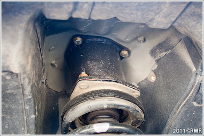
Not the best,but this CAD drawing describes it a little better. The top and bottom of the tube is where the strut flanges are mounted to.

So if you design your spacers to replicate this concept then you should be good, but do be aware that if you just run spacers and not the full Sub Frame Drop, you are going to put a wicked angle on your front CV's and when in 4WD, increase the chances of the CV's binding and eventually failing.
-Kyle
I'd argue that offset spacers are probably not necessary for under 3" of lift. I use 2" of regular strut spacers with MD OMEs and a 2.5" SFD (that is, the spacers that actually drop the subframe) and don't have alignment issues. I'll know more when I jump to 3" of strut spacers soon, but that might be the tipping point for needing camber bolts. Offset spacers, however, basically assure that you won't have alignment issues (nor need camber bolts).
i'm smelling what your stepping in.
A Sub Frame Drop does exactly that, drops the sub-frame and everything attached to it, down with.
So your controls arms, diff, hubs, and even the engine (I think) gets dropped down with it. Thats the main point by dropping the sub frame is to keep the suspension geometry the same, just mounted a few inch lower than it was originally intended.
-Kyle
Nope, the engine stays stationary. New spacers go between the motor mounts and subframe.
3" subframe drop is a 3" lift. Engine stays the same. Thats why the KRfabs kit has new engine mounts.
Sent from my Moto X
SFD is somewhat a misnomer for "lift". Dropping the subframe doesn't achieve any lift; that's something only strut spacers and/or lift springs can do. KrF's 4" SFD is a lift because it includes the 4" strut spacers. But, you could use a 4" SFD (again, subframe spacers only) with AC lift springs (~2" of lift) and 2" of strut spacers and still see ideal geometries.
In Chrome's case, 3" lift (any combo of strut spacers or springs) will warrant 3" of SFD to have stock-like geometries.
-
This thread seemed to have the best general info, aside from the fact it's for 4" spacers...
http://www.nissanpathfinders.net/forum/topic/31584-my-pathy-project-lifting/
Those spacers obviously worked, but I didn't follow those dimensions at all. My 2.5" subframe spacers measure 2.5"W x 5.75"L x 2.5"H. My 3" spacers measure 2.5"W x 5.5"L x 3"H. The <6"L is so that I don't need to bevel the passenger rear spacer to clear the brake-line cover, and so I can make all the spacers uniformly, as shown here:
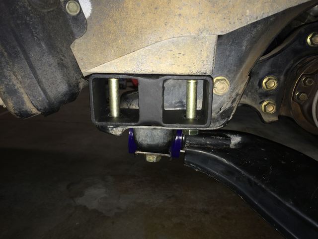
This spacer is made of 3 pieces of 2.5" square tube.
I don't have different size front and rear spacers...the only difference is the size of the bolt holes: 9/16" for the 12mm front bolts and 5/8" for the 14mm rear bolts. I also didn't see a need to offset the holes on the rear spacers; all my holes are on-centers, and you can see how that fit above. The reason those spacers shown on that thread work is because there's no unibody flange that restricts offsetting the spacer. The front, however, does have a unibody flange, and 2.5" is about the max width.
-
1
-
-
Not sure I put any sketches of mine up, but there are a few on some posts to get you started. All my bookmarks are on my other computer though, so I'll have to post those up separately.
Edit: to clarify, I mean there are some threads that still have sketches/dimensions. I have those bookmarked. You can also try searching "subframe spacer" or similar for several other related threads...the search function on the forum doesn't check terms less than 4 letters.
-
No problem. I posted a bunch of other thoughts at pics at that thread I started. The spacer sketches are on a few older posts, but I'm not big on the simple tube approach at all.
Also, whereabouts in NorCal are you? I grew up in Roseville, but find myself around the central valley 1-2 times a year.
-
Well, let me know if I can help out with any specifics. I've recorded all the sizes for all the OE bolts so that I can keep everything consistent (and metric). I've also got a complete parts list.
My 3" install next week will basically be my 4th set of spacers on the truck. I made a set of 1.5" spacers and test-fit them right before I put my 2.5" kit on. I also changed up the motor mount spacers and also upped from from .188"-wall to .250"-wall for my current 2.5" set. I've still got those spacers sitting around somewhere.
I hear you about the family friendly part. But then I see my 1- and 2-yos scale my sliders to climb into the truck and think that my truck isn't high enough to keep them out! Dare I mention all the things they've climbed to date (with my supervision).
Was the factory LSD's breakaway torque any good?
in 90-95 WD21 Pathfinders
Posted
Saw the video, too. An obvious difference, and that's the concept I'd like to go for should I be in wheel-up scenarios. But, I'm the type who needs something quantitive to describe that. I mean, is that 80 ft-lbs, or 280 ft-lbs?...can't tell without measuring. Were you just idling in for the modified take?