

hawairish
-
Posts
2,684 -
Joined
-
Last visited
-
Days Won
318
Content Type
Profiles
Forums
Calendar
Posts posted by hawairish
-
-
I agree. You'll have to let me know how the parts are when you get them, since you'll see them before I will.
No word from the eBay guy yet.
-
You could try a small L bracket on the perch and go with 8 SQI500 (the SS versions) instead. I actually have some concerns over the pulling force of the S/QIL500 anyway, but using them seems to be a more ideal setup to me.
The problem with only 1 wire loop is that nothing "resets" the side without a loop. A droop on the looped side will tug the sway bar end upwards, but when the body roll returns to center (or a droop on opposite side), nothing tugs that sway bar end back up, which means the looped side's sway bar end may actually contact something when that side's tire tucks. Both loops just allow the chassis to tug the sway bar ends to articulate the sway bar, but by not being rigid, they defeat the sway bar's function. But with only 1 loop, you'd always end up with a sway bar pointing upwards.
I think the logic applies to both front and rear axles, but it may actually be possible to pin the front bar up and skip the loops altogether. The problem is that the front sway bar's arms angle away from the wheel well, so an attachment point in the wheel well might not be close enough (or at an angle that the link can't handle). But, I like the original plan because it can be done one-handed, blindly, and you wouldn't have to go back and forth between tires to pin it up (i.e., unlink pass side, unlink driver side, pin up driver side, pin up pass side....though I guess you wouldn't need to pin up the other side?)
-
I've got a message out to a guy on eBay who sells threaded shafts and does special orders. I asked him about 1/2" sizes that I'll be going with, but also about two 3/8" options for you. The first option is just a 3/8" rod with RH threads on both sides, but the other is a 1/2" rod that's turned down to 3/8" at the ends. That way, you've got a slightly beefier option and can still have a no-drill solution (though in hindsight, I could've asked for something a little more substantial, like 5/8" or 3/4"). Regardless, we have options for beefier links at any size.
I also asked him to give some options for materials that were close to a Grade 8 zinc-plated. For me, that's all I need (dry heat here), but perhaps he's got a suitable SS option for you.
I'm going to buy a 1/2-20 die and explore making my own threaded shafts. The big box stores didn't have any UNF threaded rods, but they had steel/SS rods. An shipping is probably terrible for any sizable length of rods. I have a compound miter saw that I rigged up for chopsaw cuts (worked great for the SFD spacers).
But if push came to shove, I'm sure you could hacksaw threaded rod found locally?
Also, I was thinking about effective link lengths. For the front link, my logic might be incorrect...the "corrected" length might actually be a little less than the OE effective length. Any lift (strut spacer or lift coil) not netted out by SFD spacers cause the attachment point on the strut to actually get lower relative to the sway bar. So to keep the sway bar at it's stock (and presumably "ideal") angle, then a shorter link is needed...but there's definitely a limit to this logic. In the rear when lifted, it's moving higher relative to the sway bar, so a longer length is needed. In all likelihood, I'll leave the effective link about the same up front because I know it's working as is, but I will increase the rear link about 2".
Let me know what threaded rod lengths you come up with. I've got:
5.5" of 1/2" rod to maintain 7.5" length up front using two QI500
4.5" of 1/2" rod to maintain 7-1/8" using one QI500 and one QIL500
5.5" of 3/8" rod to maintain 7-1/8" using one QI375 and one QIL375
-
Ah yes, they had limited stock on the SS stuff. But the non-SS is zinc galvanized and should hold up pretty well.
Don't buy the rods...one side is LH thread. The disconnects are RH thread. I'm heading to Lowes in a few to check their supply if fine threaded rods...thinking they'll only have coarse thread though.
-
Well, I just ordered enough to make two sets of front and rear of disconnects. Went with the 1/2" all around. The discount volume is great...shipping was a bit pricey for UPS Ground...it was almost half the order. Total was just under $90 shipped...but enough to make 4 sets of links?! Totally worth it. If it doesn't work out, well, I have another project where these might come in handy (hint: a tailgate for the PF as part of a project rear cargo system).
About the U-bolt plate...I plan to get a plates around 1.25"W x 4"L and use them at all attachment points, front and rear. Each will have two bends: a 45° that the wire rope will loop through to keep it away from the link, and a U-shaped bend that will "wrap" the attachment point (bigger U shape for the sway bar ends, smaller/flatter U for the rear upper and strut perches. The U part will have a hole on both sides for the ball joint threaded shafts to go through; the U shape will act like a washer on both sides of the attachment point and will prevent the tab from rotating when it pulls on the sway bar (when the links are off, that is).
-
The 3/8" 90* and the 1/2" 180* are not in stock. I just checked amazon/google and it appears I will have to make some calls on monday to see if I can order over the phone from them or another distributor. Insert angry face here.
Edit: My main concern now is trying to figure out a way to keep them partially sealed so that grease can keep them lubricated. I guess we will have to take a closer look once one of us receives them, otherwise greasing them will be a weekly activity...
Where are you seeing them not in stock?
A small dab of multi-purpose should be sufficient I'd think. I doubt there's much play in the socket to need gobs of it. And judging by their drawing, there's a small pocket behind the socket where grease can reside.
-
The swaybars don't see all THAT much force, and frankly if it fails it isn't the end of the world and can be easily repaired.
I wouldn't downplay force. In fact, I think it's way more than we might expect, but I don't know how to quantify it. Think about when you're cornering...the truck wants to roll. The suspension on the outside of the turn bears weight, but the suspension on the opposite side of the vehicle does nothing to counteract it. The sway bar (I mean anti-sway bar) bears the weight on both sides...one side wants to compress the end link, and the other wants to extend. Faster speed around the corner, exponentially more force.
In experience, I've actually busted a nut (uh, yes, final answer) off a shaft-style end link (like the upper part of the rear link) on my Frontier. Not sure how, but did. So I assume the force to be significant.
oh and with regard to the spring popping out, I don't see that happening unless of course a shock fails or breaks off, either way you've got problems if that happens anyways.
Exactly.
-
Again, sorry if I came off harsh. Definitely not my intention, just saying that this thread and the previous haven't really shown us anything. You've lifted your truck, but it's a mystery how, and I'm puzzled what the point really is if you're not willing to share more details.
But you see how details just kind of trickle out, right? There's been no mention of dropping the diff. I'm very familiar with what it takes to drop the subframe, and many other components, having done all that work personally (a couple times actually). I'm very curious to know how you've accomplished it...not to bash you on how to did it, but because I'm genuinely interested to know how you solved this or that problem. I spent months hammering out tiny details just for a trivial 2.5" SFD, but I don't question its integrity at all. I think there's an upper limit using this approach, though.
Ok, so you dropped the control arm points and the differential, but obviously couldn't drop the steering rack any further because it sits above the crossmember. But why did you go this route instead of just redoing the subframe spacers? At that point, you have far more room to "safely" brace components. I'd imagine that you could build LH and RH frames (as opposed to individual spacers) that also lower the strut tower position (tied into the OE perches). By keeping the subframe completely intact, you wouldn't have to play with the OE geometries, but now you've got geometries that might be out of spec. It's good you're not seeing bumpsteer, but I'd still be cautious.
Those full-size large 6"-8" lift kits are fundamentally no different than a subframe drop:
Big brace = subframe spacers
New spindles = strut spacers
Nothing about the stock geometry changes, which I think is the best way to approach it if you just want lift.
As for no vehicle being designed for lifting, I'd disagree. As for vehicles being designed to be lifted 9"-12", I totally agree for just about anything lacking straight axles (except older Fords with the I-beam style front axles like Rangers and Explorers). Nothing impossible, just some ways are better than others.
In all seriousness, I'd love to see more pictures and have this be something we see more of down the line. Again, it's the whole "building it up for the next owner" thing that baffles me. When I sold my Jeep...I pulled off lift springs, sliders, guards...everything...because they added nominal value to the trade-in. Then I sold everything to Joe Jeeper for as much as I paid for them (if not more). That's where the diminishing returns comment came in. Wouldn't it be reasonable to focus your energy and money on the next project?
-
Thoughts:
1. Ideally, I'd like to have a no-drill solution for both front and rear. Problem is that the 3/8" components are a little smaller in all proportions to the 1/2" links. That means a thinner threaded rod (and thinner than OE), but also about 1" more exposed thread than if it were 1/2". It seems plausible that a 3/8" link might be weaker than OE. As such, a 1/2" link seems more appropriate for the rear, even if it requires drilling holes wider. (The fronts will be 1/2")
2. Conveniently, 1/2" components are cheaper than 3/8" no matter how you spin it, so I will go the 1/2" route front and rear.
3. MCP has this little blurb on their Warranties page: "Ball Joints (ie: ES, ESA, Qi, SQi series, etc.) are very light duty; they are typically used only in hand or foot actuated linkages." I'm struggling a little with this one. Steinjager was born from MCP...it actually says that on their website. So why would I think that MCP sells a "very light duty" component that isn't suitable for the SJ link? The rest of their warranty page basically says, "don't quote us on strengths for anything we sell".
4. I didn't see much for reviews on the SJ links. There's a Youtube vid that a Jeeper posted up, but that guy also got completely (and unnecessarily) flamed by other Jeep f*ckheads for even putting disconnects on a Jeep (and that his frame was rusty). The problem with discos on a Jeep is that the wheel base and controls arms are too short, which leads to a higher potential of popping a spring on lifted Jeeps, and I think that's the point they were (poorly) trying to make. I think it's less of a problem for us, but I'm open to concerns. This can only be tested to some degree on a shop floor.
5. I was exploring 1/8" wire rope (i.e., steel cable, steel lanyard) options looped through a u-bolt plate/strap with some bends on it. This would attach with the hardware and would only come into play when the link is removed. I'd have to sketch this out so you have a better idea of its shape/function.
On a side note...maybe we should ask a moderator to rename this thread in the spirit of DIY disconnects?

-
the rear a-arm bar is one bar that goes from one a arm to the other. it has a big curve in it to go over the front driveshaft. i know a little bit of bump steer will ocure but not too much hopefully. fot the rear i plan to put a little spacer in the driveshaft and extend the links out a little less than an inch. also get new longer coils. i will need a longer diff breathing hose and also a longer drop panhard drop bracket.
The front driveshaft doesn't articulate, and is above the plane between the control arms' rear mounts...so why'd you go over the driveshaft? I also agree with XPLORx4...I think you will have a lot of bumpsteer and it will track poorly, with high probability of bent tie-rods.
Still, why go through all this effort if you're trying to sell it? I really think you've reached the point of diminishing returns. We'd get it if you were planning to keep it and wheel it, but that doesn't seem to be the case.
To be frank, I've not seen anything that would make me trust your setup, and nothing about this post or the previous 9" Lift! posts seems to make sense to me. I want to be awed, but it hasn't happened. I totally get what you're trying to do and how to accomplish it, but I have serious concerns that it's being done correctly or safely, and I think (hope) the community feels this way.
You're flaunting that you've got some ungodly amount of lift on a vehicle that responds poorly to, and is simply not designed for, ungodly amounts of lift without real fabrication. Yet you're completely vague on the details, and the pics just leave us hanging. Either you lack pride and ingenuity in your work, or you secretly acknowledge it might not be safe, but hey: 12" Lift!
Again, I really don't want to sound like a dick here (and maybe it's too late for that), but I hope this doesn't see action on the road anytime soon.
If my intention was to sell two trucks, I'd be returning one to stock height, selling both separately as-is (or scrapping the donor), selling a tire/wheel package for a pretty penny to some Chevy/Toyota guy, and scrapping some steel. In a dream world, I'd have sold the donor truck, pulled the subframe, and begun SAS'ing it.
-
I presume the tolerance will be snug, so minimal noise if any. But, I'd plan on greasing the sockets regardless, which will suppress noise.
The OE rear links are 7-1/8" (effective length from bottom of perch to socket center), and the front links are 7-1/2" socket center-center. The actual length of the completed link will be longer than those values, of course.
The precision of the length is somewhat arbitrary, though. For the rear, the effective length should technically increase equally with the amount of lift. In the front, the effective length should change by the amount of lift (strut spacers and coils) less subframe drop height (for those with SFDs, of course). Both calculations put the sway bar at stock angles.
In my case, I'll probably make my rear links about 2" longer, but the fronts will stay the same length. But really, the stock rear length appears fine, so maybe I won't change it much.
I'm crunching the numbers now. The thread depth of the joints don't allow much for adjustable length, but I don't see that as necessary.
The crappy part is that even if I order these up soon, I won't be able to touch them for a couple weeks due to work travel.
-
LOL: These guys are 5 blocks from each other.
Midwest Control Products Corp., 590 East Main Street, Bushnell, IL 61422 USA
Steinjäger, Inc. Hwy 9 West Box 299, Bushnell, IL 61422
Anyone want me to make some extra sets? Volume discounts!
-
I was thinking a pool noodle or pipe insulation and duct tape...pad up the hoop and let it rest on the differential. But, I'm convinced that a strap/cable would work just fine. I'll have to rig up a model of some sort to confirm.
BUT DUDE: DIY DISCONNECTS!
I Googled "ball joint quick disconnects" on a hunch. That first pic I posted (made by Steinjäger) appears to have been made entirely by parts from Midwest Control. They have an impression selection, detailed website, and do online orders. So, here's what I'm thinking...
2x QIL375 180° @ $12.66/ea for the upper rear perches:
http://www.midwestcontrol.com/part.php?id=128

2x QI375 90° @ $3.45/ea for rear sway bar
http://www.midwestcontrol.com/part.php?id=115

4x QI500 @ $3.76/ea for the fronts
http://www.midwestcontrol.com/part.php?id=116
The OE rear links have 10mm studs and fronts are 12mm. These rears would be 3/8-24 (9.5mm) and 1/2-20 (12.7mm). You'd barely need to enlarge the front sway bar eyelets a trivial amount. They have metric disconnects, too (see QM10 and QM12), but not for the 180° joint; metrics are also a little more expensive, but not by much.
They sell threaded linkages, but with an LH and RH thread. I didn't see any disconnects as LH thread, though. I sent them an email to see if they do RH/RH links, since their links look better than a simple threaded rod, and they do various lengths for a couple bucks each. They also sell the jam nuts.
We're looking at $50 in parts for front AND rear links!
Midwest also sells heim joints so you could make your own link exactly like the Steinjäger ones. Assuming the parts are the same, I think these will also have plenty of strength.
Since these can be removed/installed with one hand, I also did a simple test: I can touch the ends of each link on my truck by just reaching around the tire. And that's without having to lay on the ground. All that remains on after the link is disconnect are little ball joint studs and the limit straps. The link disconnects in one piece.
Something tells me I'm making a purchase tonight. I'll probably go with 1/2-20 (QI500/QIL500) all around so I can just buy a 2' length of threaded rod, cut it down, maybe sleeve it with heat shrink or flexible tubing to keep the elements off it. Their volume discounts even start at 2 pieces.
I'm gonna be losing sleep tonight thinking about how bad ass this is going to be!
(Sorry for the long post...excited.)
-
I'm glad you're open to the suggestions and constructive criticism here. And definitely don't get me wrong...I totally applaud the effort.
We'd need to see better pics of how you did the strut spacers, subframe spacers, and rear control arm blocks to give good feedback.
I'm particularly curious to see how you spaced the rear control arm bushings. Did you just do individual spacers, or a full-length tube between the two? The latter would be a good way to achieve the 'missing link', but could also be a tie-in point for running support tubes to some point near the transmission crossmember mounting bolts. I think you basically just need a way to support your stilt-like stance, evident from the front-side pic. That's the pic that shocks me the most.
-
 2
2
-
-
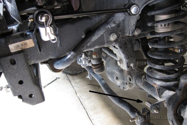
So I just went out and looked at it again, and I don't think that would work. Our swaybar is attached to the rear axle as a fixed location instead of the chassis like that photo depicts. Therefore, it would actually make more sense to disconnect at the sway I think. Could you zip tie the swaybar to the rear lower control arm? My head isn't working right to figure out the physics of that at the momemnt...will think some more.
You have to pin it to whatever the sway bar is mounted to, otherwise you're not defeating the sway bar.
My plan was to fab a ~6" or so bracket and attach it at the bolt just below the spring (one of the bolts that secures the sway bar to the axle). That way I'd disconnect from the upper perch and attach to the bracket.
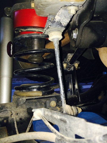
But while taking this pic, it might actually be a minor pain to conn/disconn. For sure, you'd have to be on the ground to do it, and would have to reach a point that's nearly an arm's length away. Perhaps another approach is in order...
I think the solution is some sort of limiting strap, like a nylon strap or rope with eyelets. They'd connect between the chassis/perch and sway bar end at the same or similar points as the disconnect link. When the link is in place, the strap has no effect. When removed, the straps will prevent the sway bar ends from dipping lower, but without inhibiting either end from traveling up when the truck is flexing (1 wheel up, 1 wheel down). When the truck is level, the bar will return to level.
This approach would need the link to be removed or pinned to something. The nice part about this approach is that the link (if it stayed connected to the sway bar) could just be strapped to the sway bar itself. The limiting straps wouldn't need to be nearly as robust as true limiting straps.
Not sure I've seen a setup like this, either. Some kits come with nylon strapping, but it's for pinning up the disconnected link.
-
Good luck!
-
With regard to keeping the sway bar in check, couldn't you only remove one of the sides? That in theory would make it useless but still attached enough not to bang around....
I've come to that same conclusion. But, I've never seen disconnects sold just as one, so there must be something fundamental or cool about having a pair. I don't see any problem with just having one attached, except a possibility that under some flex, the sway bar hits the top of the 3rd member, or swings backwards and hits brake lines or LSV components. I don't have a LSV so the latter isn't applicable to me.
These are the ones that I was referring to.
Yep, that would work on the rear. I've seen cheaper variants, but basically the studded could attach to the upper perch on the truck and disconnects at the sway bar.
But this is why I'd prefer the disconnect to stay connected to the sway bar end and detach from the upper perch:
This way you can pin the sway bar to a 3rd point somewhere on the axle.
-
It's a miracle!
But, to adamzan's point, did you use OE rubber bushings or poly? If you did poly, and you greased them up right, then you can torque them while still in the air. If you did OE rubber, then adamzan is right...gotta torque them on the ground and normal load.
However, I'm not sure it would've had the effect you experienced...if you torqued them while in the air, the preload on the bushings would've helped lift it, not cause it to sag.
-
I don't have firsthand experience, but I wasn't impressed by them. The design (and at that price) solves more problems than it creates.
I wouldn't be terribly concerned about having to drill the sway bar if you plan to return to stock. The stock hole is 10mm, and you're increasing it a little under 3mm. There will be a little wiggle room, but adding a flat washer on the link side will help sandwich the sway bar end appropriately.
What I don't like about the link is that once you've disconnected it, there's nothing that stops the sway bar from rotating downward about 30-40° to the point where the upper hoop of the sway bar is resting on the 3rd member and the sway bar ends are sitting a few inches lower than the axle and snagging on rocks. There needs to be a way to anchor the end of the disconnect to the axle so it doesn't interfere with anything.
I also why I don't see the need for 4 disconnect points. Just more parts to take off. A lot of Jeep ones have brackets/straps so you can pin everything up, which I like. I wonder about noise, too....D-clips and metal-metal contact everywhere.
I've been eyeballing something like this:

http://midwestjeepwillys.com/j0031036-wrangler-jk-disconnect-rear-sway-bar-links-2-5-lift.html
They're adjustable length, the link stays attached to the sway bar, and it it's a one-hand, no-loose-parts disconnect. You'd need some sort of L bracket on the upper mount for the ball head bolt to attach to, and an extra set of ball head bolts and another custom bracket on the axle to attach to so that it stays out of the way. This is also $50 cheaper than the AC, which I think are just universal parts from Warrior Products.
This particular link style would work on the fronts as-is I think, but it depends on if the quick-release head rotates at all.
Otherwise, there are a few Rough Country ones that could work well, too, just need create a bracket for mounting them to the upper link perches. They're also much cheaper than others.
http://www.roughcountry.com/suspension-components/sway-bar-kits.html?limit=21
-
Yeah, I gotta echo Kingman's concerns while trying to not be a dick. Even after those points he mentioned are addressed, you've added a lot more leverage by lowering the control arm points. The pictures don't give nearly enough details as to how, but it doesn't look like there's anything that improves how the subframe is secured to the unibody, like lateral tie-in bars that connect further under the chassis to reduce flex or distribute load. It just seems like a house of cards waiting to topple.
Since you had previously stacked SFD spacers (and consequently added additional hardware), you've really just put a lot more stress on those components. My worry is that a good forward bump at the wheels will just pop some nuts off (best case scenario); this could be as simple as coming down a hill and meeting flat surface, where much of the body weight is focused over the front suspension. If those don't give, the unibody pays the price by flexing more than it was intended to.
If you're selling it, though, why put the extra energy/money into lifting it more, anyway? I mean, I hope you find the right buyer, but I think you may already be limiting your target audience. Is it also a package deal that they take your other PF?
-
What do you mean as alignment pins? When you say that I think of the bell housing and block dowel holes. If that's the case yes they are line up well just away from each other the better part of an inch.
LOL I love that description.
Yep, alignment pins = dowels.
That's about as accurate as I could have described it. It wasn't fun. I could've added "prison-inmate" somewhere in there.
You may just need to find a way to support the transmission loosely enough to allow pitching/rolling/lifting it to get the angle right. I had to lift the rear of the transmission more than I expected, then it just slid right in to a decent gap and I used the bolts to draw it closed.
-
I think I misread your original post. You're just looking for a way to close the gap between your transmission and engine so you can bolt them back together? Do the motor mounts connect to the subframe without issue?
Is it possible you just need to rotate the input shaft a little to get them to line up, or maybe adjust the insertion angle? With the transmission crossmember off, how are you supporting the transmission? Can you see any alignment pins that might be out of line?
I had a similar problem when changing a Frontier clutch long ago. I had to upside-down-bear-hug-dry-hump-lift-twist the transmission to get the splines to line up and close the gap. It doesn't take much of an angle to prevent it from sliding forward apparently.
-
Motor mounts are the same on each side, and there's really only one way to mount them. One side has a stud and an alignment nub, the other side has two studs. The two studs point straight down, but the alignment nub would prevent mounting them incorrectly on the engine brackets.
However, judging by the image below, the brackets (11232 and 11233) are side-dependent, but I'd be surprised if they had the same bolt patterns. They might have some stamp indicating side (LH, RH) or direction (arrow towards front of vehicle).
If those are right, maybe you just need to loosen the transmission mount and shift the engine over, then re-tighten the mount?

-
Don't know why it didn't cross my mind earlier, but just go here: http://www.nissanusa.com/recalls-vin. The dealership will cover the costs of any recalls.
I've got an 04 SE and mine turned up negative. Though, that's not to say a recall is still in the works...I haven't been following the issue closely.
My vehicle made the air bag recall list finally. Might want to check yours out at the link above.
4x4 parts rear swaybar disconnects
in 96-2004 R50 Pathfinders
Posted
Guess that's a good thing. I mean, we've spelled out the concept clearly so hopefully anyone who's looking for a solution finds it here. Also hope they chime in with their results to keep this as a resourceful thread for everyone.