- Sign In Changes: You now need to sign in using the email address associated with your account, combined with your current password. Using your display name and password is no longer supported.
- If you are currently trying to register, are not receiving the validation email, and are using an Outlook, Hotmail or Yahoo domain email address, please change your email address to something other than those (or temporary email providers). These domains are known to have problems delivering emails from the community.
Leaderboard



Popular Content
Showing content with the highest reputation on 02/20/2023 in all areas
-
No idea. Assuming the cluster stores the info on board, I imagine it would probably work. Check the '97 and '98 service manuals to see if the pinout is the same.1 point
-
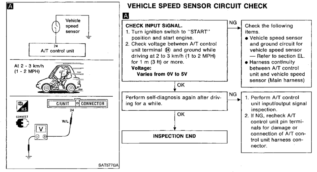
@Slartibartfast Thanks for the super helpful response! I followed the diagnostic flow charts in the service manual (relevant pages seemed to be EF&EC-38, EF&EC-39, AT-39 through AT-42, and wiring diagrams on AT-36 through AT-38). You're right on the money, ECM has a code for 14--vehicle speed sensor. Going through the diagnostics in the AT section showed that "Vehicle speed sensor circuit is short circuited or disconnected" (AT-40). This prompted me to check the voltage at terminal 24, see attached screenshot from the manual. I'm a little confused by this check--am I supposed to measure the voltage at the harness when it is disconnected? Or am I somehow supposed to measure the voltage at this terminal when the harness is connected to the control unit (not sure how I would do the latter)? I disconnected the harnesses from the A/T control unit and measured the harness side voltage while my dad was driving 1-2 mph. I was seeing readings of 1-3 V, which supposedly is normal according to this flow chart. The spec of 0-5V shown in the flow chart seems super vague though. Any ideas on where to go next? One other thing I noticed: the diagram on AT-38 shows the vehicle speed sensor going through the speedometer before going to the ECM and A/T control unit. So since my speedometer isn't working, and yet my A/T control unit is apparently getting an acceptable signal (if I did the test correctly), wouldn't this narrow the problem down to the speedometer servo motor (or whatever physically drives the needle)? Although this wouldn't explain the engine code...
 1 point