- Sign In Changes: You now need to sign in using the email address associated with your account, combined with your current password. Using your display name and password is no longer supported.
- If you are currently trying to register, are not receiving the validation email, and are using an Outlook, Hotmail or Yahoo domain email address, please change your email address to something other than those (or temporary email providers). These domains are known to have problems delivering emails from the community.


muniman01
-
Posts
8 -
Joined
-
Last visited
muniman01's Achievements
NPORA Newbie (1/5)
3
Reputation
-
Speedometer/Odometer stuck at 0 on 1995 Pathfinder
muniman01 replied to muniman01's topic in 90-95 WD21 Pathfinders
Got it off, just took some more force! It’s all back together now with the new speedometer gear, I just got to let the silicone dry before filling back up with oil. The speedometer gear was VERY worn out. Had some hiccups along the way. Mainly getting that cover back in place was a pain in the rear, so I’m kinda concerned about the quality of the silicone seal. Also, I lost my reference on one of the torsion bars so will have to adjust that one back to level once I drop the truck off to the jackstands. I’ll update y’all once I finish it up. Probably won’t be this week unfortunately. -
Speedometer/Odometer stuck at 0 on 1995 Pathfinder
muniman01 replied to muniman01's topic in 90-95 WD21 Pathfinders
Ok, I’m into this project now. I’ve got the driveshaft, torsion bar, and torsion bar crossmember off (I’ve also drained the fluid). I’m hoping to just need to remove the rear cover, not the entire transfer case. So I’ve got all the bolts for this rear cover off and the cover is sticking; it won’t budge. There are some pry points that I’ve pried from with a flathead screwdriver. I could pry harder or introduce a rubber mallet, but I’m concerned about inflicting damage. Do I just need to bring more force or is there a trick that I am missing? I’m also slightly concerned that parts inside the transmission/transfer case are being supported by this rear cover and will fall off once I remove it—and potentially be super challenging to install back together again. Kinda just moving ahead anyways, but would welcome any wisdom on whether this is a legitimate concern. -
Speedometer/Odometer stuck at 0 on 1995 Pathfinder
muniman01 replied to muniman01's topic in 90-95 WD21 Pathfinders
Well, I've thought about it some and finally decided I'll make the effort to fix this. Just ordered both gears. I'll take any and all advice for cracking the AT open (and getting it back together again)! Also if you know of any tools/stuff I will need other than basic hand tools let me know so I can get them in advance. So when I seal it back up, I can just use any old silicone, or is there a specialty formula that I need to use? -
Speedometer/Odometer stuck at 0 on 1995 Pathfinder
muniman01 replied to muniman01's topic in 90-95 WD21 Pathfinders
So I put the sensor back in, hooked up my "oscilloscope" and spun the driveshaft only to see no waveform. Then I pulled the sensor out and peered in and found that the gear inside the transmission is also worn down, although slightly more than the one of the sensor. With both of these worn down, they are just no longer grabbing. I'm happy because I've finally found the problem; but I don't think fixing this is worth it to me. I would have to disassemble the rear transmission casing in order replace that gear. Historically, I don't have good relationships with gaskets and aluminum cases. But, if someone chimes in saying that this is an easy disassembly I might consider it. Otherwise, I'm going to live without a speedo/odometer. Thanks for the help @Slartibartfast, your wisdom is much appreciated!- 15 replies
-
- 2
-

-
- wd21 pathfinder vg30
- 1995
- (and 5 more)
-
Speedometer/Odometer stuck at 0 on 1995 Pathfinder
muniman01 replied to muniman01's topic in 90-95 WD21 Pathfinders
Well, the sensor does not appear to be the issue. The new sensor arrived today so I took the old one out, only to realize that the shaft of the new sensor is shorter and so is not a direct replacement. While I had the one out though, I figured I'd do some more testing. I unfortunately do not have an oscilloscope, but I rigged up a simple program on my Arduino to test resistance vs time of the sensor. The old sensor behaves quite similarly to the new one -- it's around 300 ohms at rest, and then runs about 4 periods of a waveform when the shaft is rotated one full turn. The old sensor does not feel as smooth (which is evident in a slightly more jagged waveform) and also does not have quite as large of an amplitude. However, if seems to behave similarly enough that I doubt this is my problem. One thing I did notice is that the gear was a tiny bit worn down. Same deal, I don't think this is enough to cause my problem. I suppose that once I put the old sensor back in I could plug my "oscilloscope" into it again to make sure that the driveshaft is turning the gear. I have pictures of the waveform that would be fun to share, but they are a few hundred kB. It looks like the max upload for a post here is 8.45 kB--how do I work around this limit? -
Speedometer/Odometer stuck at 0 on 1995 Pathfinder
muniman01 replied to muniman01's topic in 90-95 WD21 Pathfinders
Ok, I've been busy with life but have finally gotten a chance to perform some of these tests. I tested the voltage at the A/T control unit again except with the connector installed. This time, it read a constant ~5V while moving along at 1-2 MPH. So clearly, not the square wave that it should be. Next, I tested the continuity from the this wire to where it comes from behind the console. I used the wiring diagram on AT36-AT37 to find the correct terminals. The continuity was good (1-2 ohms). Next, I tested the continuity of the reed switch itself. I believe it is the sensor at the back passenger side of the transmission that looks like this (https://www.oreillyauto.com/detail/c/import-direct-ignition/brakes/anti-lock-brake--abs--parts/vehicle-speed-sensor/e06e4f5f9dc5/import-direct-ignition-2-terminal-vehicle-speed-sensor/odi0/130122/v/a/6749/automotive-suv-1995-nissan-pathfinder?pos=0) I was getting an open circuit at this sensor regardless of where I had the driveshaft positioned. Based on this, I must assume that this sensor is the problem. However, if the reed switch truly is stuck open I would have guessed that I would see 0 V at the A/T control unit terminal from this sensor rather than the 5 V I was seeing-assuming the 5 V signal is sent through this switch and then directly to the control unit. But who knows, maybe the circuit pulls the terminal at the A/T control unit to 0 when the switch closes. I am wondering, could a sensor like this really cause (what started as) an intermittent problem? So, I'll plan on replacing this sensor and see if that solves my issue. Can I simply replace the sensor without draining any fluid, or will fluid come spilling out of the cavity when I remove the old sensor? -
Speedometer/Odometer stuck at 0 on 1995 Pathfinder
muniman01 replied to muniman01's topic in 90-95 WD21 Pathfinders
@Slartibartfast Thanks for the super helpful response! I followed the diagnostic flow charts in the service manual (relevant pages seemed to be EF&EC-38, EF&EC-39, AT-39 through AT-42, and wiring diagrams on AT-36 through AT-38). You're right on the money, ECM has a code for 14--vehicle speed sensor. Going through the diagnostics in the AT section showed that "Vehicle speed sensor circuit is short circuited or disconnected" (AT-40). This prompted me to check the voltage at terminal 24, see attached screenshot from the manual. I'm a little confused by this check--am I supposed to measure the voltage at the harness when it is disconnected? Or am I somehow supposed to measure the voltage at this terminal when the harness is connected to the control unit (not sure how I would do the latter)? I disconnected the harnesses from the A/T control unit and measured the harness side voltage while my dad was driving 1-2 mph. I was seeing readings of 1-3 V, which supposedly is normal according to this flow chart. The spec of 0-5V shown in the flow chart seems super vague though. Any ideas on where to go next? One other thing I noticed: the diagram on AT-38 shows the vehicle speed sensor going through the speedometer before going to the ECM and A/T control unit. So since my speedometer isn't working, and yet my A/T control unit is apparently getting an acceptable signal (if I did the test correctly), wouldn't this narrow the problem down to the speedometer servo motor (or whatever physically drives the needle)? Although this wouldn't explain the engine code...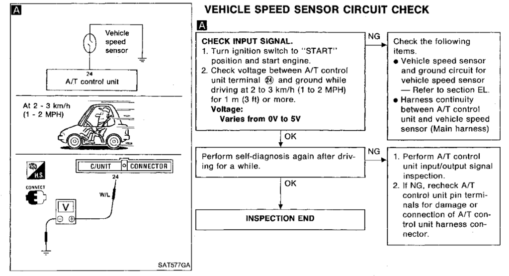
- 15 replies
-
- 1
-
-
- wd21 pathfinder vg30
- 1995
- (and 5 more)
-
Ok folks, I'm trying to fix my speedometer/odometer in my 1995 Nissan pathfinder. I know this is a somewhat common problem, and have looked through some other helpful posts. Still struggling to find exact details for my specific year. So, I bought a Chilton repair manual thinking it would have all the electrical diagrams to be able to diagnose this, but alas it wasn't that helpful. I couldn't find any detailed wiring diagrams specifically for the dash. Any tips from the experts on where I can find a schematic showing what is supposed to be at each wire in the harness? Or just any tips in general on diagnosing this? For completeness, here's the symptoms: A few months back the speedometer started getting twitchy. It would twitch down as you are driving at a constant speed--it never twitched above your true speed (checked with GPS watch). Then, this worsened and eventually got to the point where it would stop working altogether and stay at 0. Often times when the speedometer is stuck at zero the check engine light is also on. The times when it was stuck at zero (as opposed to being twitchy) eventually became more and more common, until now it is always stuck at zero with the check engine light on. The odometer also does not work when the speedometer is stuck at zero. Transmission seems to be functioning normally. Really appreciate any and all help!
