- Sign In Changes: You now need to sign in using the email address associated with your account, combined with your current password. Using your display name and password is no longer supported.
- If you are currently trying to register, are not receiving the validation email, and are using an Outlook, Hotmail or Yahoo domain email address, please change your email address to something other than those (or temporary email providers). These domains are known to have problems delivering emails from the community.
Leaderboard


Popular Content
Showing content with the highest reputation on 08/31/2020 in Posts
-
That part is simply a metal brace to provide backup support for the splash guard. It's not terribly important if you choose to remove it, and it's probably preferable to replace the splash guard and the brace with a genuine skid plate such as this one: https://sfcreation.com/products/front-skidplate-14-aluminium2 points
-
Finally, after around 16 hours of fighting with almost every single nut & bolt, the front is done (except alignment of course)!! I didn't take any pics along the way because of the frustration of having to heat almost every fastener up with the torch, breaker bar w/4ft cheater pipe, high torque impact gun, you get the idea, but I only snapped 1 little bolt off (one that holds the bracket of nonsense on top of the drivers side strut tower and a bunch on the hubs). Had to ditch my Mile Marker hubs, as they were locked in the lock position and when I was attempting to take them apart, damn near every one of the little bolts that hold the "cap" on snapped. Once I got them off I inspected and repacked the wheel bearings, then put it back together with the stock drive flanges (thank God I saved them!). She drives good, now has about an inch & a half "Cali-lean" going on, but that'll be addressed midweek when I tackle the rear. Time for a hot shower and a cold beer... Sent from my Mobile Communications Device2 points
-
That shock will have 16mm eyes on both sides. Pathfinders are 12mm and 16mm. The location of the 12mm goes from the lower mount to the upper mount at the 1999.5 model year1 point
-
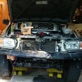
Update, so for the past week and half. the truck been slowly worked on, sitting on the hoist. Removing parts when i can come in, been getting help from the shop, Nissan Seals/Gaskets been a waiting game as we go along and see things that are needed Week ago, i installed these new belts lol off they come again to remove upper oil pan Under Carriage was pretty clean in turn made the removal of parts much easier Rear Main Seal This crush washer above the RMS was probably the longest wait Cleaning the upper oil pan and lower Box of hardware for the lift top to bottom. All Nissan parts except rear bump stop TO BE CONTINUE......1 point
-
Yes, the larger pipe has the low side port. If it isn't getting cold, that is telling me that either the refrigerant isn't flowing or flowing too much. Is the small pipe hot? Either way, it sounds like your problem is not the temperature door. With the AC on and engine running, the hub of the AC pulley is turning with the pulley, correct? If so, you will need a set of pressure gauges to see what is going on. General rule of thumb I have seen with most ac systems, with ambiant temperature about 80-90°f, the low side should be about 30-40 psi and high side about 200-250 psi. If both are low, then the charge is usually low. If both are high, then the system is usually over charged. If the low side is low, high side normal or high, usually a restriction on the system. Low side pressure high with high side low or normal usually indicates an expansion valve stuck open. If both the high and low are close to the same, usually indicates a failed compressor. Fluttering needles on the gauges, usually happens on the high side, indicates failing valves in the compressor. If the hub of the compressor pulley is not turning or starts and stops frequently, you have either a pressure switch or electrical problem. All this assumes that your AC has a proper charge +/- 1/2 pound of 134a refrigerant.1 point
-
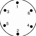
Well, the distributor would be off, but don't believe it would be 180°, you have a 6 cyl 4 cycle engine. My mind is tired and don't really want to figure all the variables. I find it easier to just ensure TDC compression. You can do this by pulling #1 plug, put something like a cotton ball in the hole and turn the crankshaft by hand while watching the ball. When it pops up, you know you are on the compression stroke. Then you can use a long screwdriver or other rod that is long enough to reach the piston top. Watching the rod, turn the crankshaft until the rod hits it's highest point. That will have you at TDC compression. Then you can install the distributor with the rotor arm pointing to #1 tower on the cap. I find it easier to mark the base of the distributor where #1 is so aligning that rotor is easier. Set the distributor into place and see how far the rotor turns. Then pull the distributor back out, turn the rotor the same distance the opposite side of the mark. Then when you put the distributor back in, the rotor should be lined up with your mark. That should get you pretty much at 0° TDC. You should be able to get the engine to start and finish setting the base timing.1 point
-
Daytripping in the Cascade Foothills with@TowndawgR501 point