

ejin4499
-
Posts
358 -
Joined
-
Last visited
Content Type
Profiles
Forums
Calendar
Posts posted by ejin4499
-
-
you might consider getting some nitrogen and freezing the new one so it shrinks down some before you put it in. I don't know what liquid nitrogen would do to the rubber but the metal would be fine.
-
Sorry I just have to ask the obvious question. Why not just go get a complete harness from a yard? For my expenses I'd ship you a injection harness from Cali as long as you don't need it in a hurry.
-
Assuming all the time in the world to do things slowly and as cash permits I would pull everything down to the bare metal, save what is still in decent shape for later, get a donor vehicle and swap everything over wholesale. If I had an option I would get something with a VQ engine. Then once I know how heavy the engine is going to be SAS it.
-
The wiring isn't that bad three or four plugs to rewire on the harness but a donor vehicle would be really really nice to have. If you don't have that then make sure you read up on what people take out for the manual swap so you know what you need to put back in.
If memory serves you would need a
- Tranny computer all the wiring from that (look under driver side seat)
- The key lock in the ignition
- Harness from the tranny to the shifter
- Harness from tranny to engine bay
- Compatible speed sensor yours being an 88 would have a mechanical speed sensor i think you can take yours and put it on a newer automatic but you may want better confirmation than that.
- You're going to have to do something about the clutch pedal and neutral safety switches and interlock switches
- There is a switch for changing something about how the tranny shifts to the left of the steering column don't know if you need that or not but its there.
Good luck hope that gets your started
-
Sealed mine up with grey rtv can't even tell it's there. Used it like it was spakle.
-
Napa checking in. I'm looking forward to meeting folks in person.
-
If it's a cable driven speedometer it could also be off at the speedometer itself, not likely as you have to take the speedometer completely out of the cluster to mess it up.
I also can explain how to calibrate the speedo at the speedometer itself if needed.
that info would be awesom just to have if you can post it.
-
what year maxima is that fan out of?
-
I have had the maf O rings get old and lose a seal. You might be hearing air whistle through that.
-
you could always just weld it

-
I wonder if this console would fit better in the WD21 than the R50 or Jeep one, just found this in a hardbody brochure,

Did anyone ever try to swap the hardbody ebrake to the pathfinder? I remember a thread on it but couldn't find it.

-
Sounds like a lot of work and money to not get gains that would make it worthwhile.
As stated before it depends on if you have made other mods to your engine. stock engine absolutely not worth it larger engine with better exhaust maybe.
-
Update
Found a patrol website (foreign cousin of the pathfinder right?)
http://www.patrol4x4.com/forum/general-patrol-discussion-17/donator-maf-sensor-booster-65671/
Where they discuss a voltage modifier. Tell me this doesn't sound like exactly what I was trying to do but better because its programmable.
also found this
-
Ours is a hot wire element not a vane type MAF. The fsm only posts 1 temp vs voltage output at idle no load. The fsm for the 97 posts 2 idle and 2500 rpm. As Nefarious pointed out there is some where around 100 different steps. I need enough points to estimate the current maf curve and then see if I can match that curve with a different hot wire. My hope is that I can make the same shape maf curve with the new element but make the MAF report that the air has more mass than it really does. If the computer thinks the air has more mass it will richen up the mixture. Once I know how much then I can tune the bore to the right size for the new element.
-
Does anyone know where I can find any specific documentation about our maf. The only thing I am able to find is generic to MAFs in general. I'm hoping for a break down of what its output vs input is and what the darn thing is made out of. I am reasonably sure that it is a platinum resistor similar to what is used in thermometers but I would love some manufacturer specs on it.
-
If the throttle opens too fast, you're just going to burn out. Maybe I explained it weird. It's all about throttle response right? Say your car comes with a 60mm throttle body, that's pretty big. But, an NA engine is only going to suck as much air as it physically can. So lets say you upgrade to a 75mm or whatever and the motor is optimal with a 70mm. The engine is going to be at WOT before the pedal is all the way to the floor. What's the point? Now, people get crazy and bigger is better right? Let's put the 90mm throttle body from a Q45 on this thing and still N/A. The engine is going to be wide open before you even reach 50% of the pedal travel.
Read this thread from hybridZ, lots of good info: http://forums.hybridz.org/topic/54034-big-throttle-bodies-why/
Ok I totaly understand that, but where I'm lost is we are talking about making the MAF bore larger not the throttle body.
The other part of this discussion wich is unstated is that some of us are using a VG33 block on VG30 equipment. How can we uncork the intake so we can make the most of that bigger block?
To me the throttle is the easy part to figure out. Bore it out and put a bigger plate in there. The tricky part is the maf. How can we open that up without having to reprogram the ecu for a new sensor? Thus my question what is the hot wire in the existing maf and can we replace it with a bigger lower resistance one to recalibrate the sensor for a larger bore/maf body?
-
Unless he was trying to dial his rig in for a certain speed would changing the gears really net him any better mileage?
-
The factory one is probably overkill and over priced. I'll get a new magnaflow and see if they will smog me again.
They wanted me to go to the "Smog Referee" because its an engine CHANGE not an engine REPLACEMENT.
Both TBI and MPFI are listed as fuel injected vehicles but the engine appearance not matching the vacuum diagram under the hood set them off a little and when I failed the tail pipe emissions they said no way, see the Referee...
why not swap your hood with a MPFI pathie so the vacuum diagram matches what you have? How would they know at that point?
-
4 cylinder engines use big MAFs to make them more drivable. Going too large just makes anything undrivable, that's why the Q45 throttle body is not linear.
It is interesting that the maxima uses a larger MAF than the other VG equipped vehicles. But it's also interesting that they use the n60 MAF in both the VG30E and the VE30DE.
Can't say you'll actually see any improvement in the real world as the restriction in the VG**E is that intake manifold was designed with forced induction in mind.
Could you go into what you mean by un-driveable? I always figured more air means more power and on naturally aspirated engines more air means less restriction.
-
You can buy individual maf elements but they won't work properly with an factory ecu. It's not so much the amplitude of the 0-5 v signal, its the analog steps between those voltages called the "maf curve". Each style of maf has different voltage steps based on temp than another maf.
For example one maf may put out 1.1v at temp1, 2.3v at temp2 and 4v at temp3
Where's another maf may put out .8v at temp1, .2.5v at temp2 and 3.8v at temp3.
There are far more than 3 steps since the analog signal is converted to digital for use in the ecu. There are usually 40-100 analog levels that convert over to digital so just plugging and playing with a new maf element (although u may get it to work) is really not ideal because even if it runs fine under some rpm/load conditions, it most likely will not run all values correctly.
Even the difference between an n60 maf and n62 maf is enormous, value wise, and they share identical maf housing even with just different elements.
I am currently working on setting up a stock ecu with a programmable tune to utilize a larger maf and more aggressive afr and timing curves. I'm finishing up my second year of industrial electronics/automation diploma so time is tight but I will definitely have a setup going in the new year.
My plan is to run an n60 maf and some slightly larger injectors (possibly 260cc from a ka24de) to keep the duty cycle and pulse width low. This uses the same housing as a n62 (around 3" diameter air passage, much bigger than the 1.75" stock maf air passage) and doesn't get near 5v output until over 300 HP. They can be had quite cheaply as well.
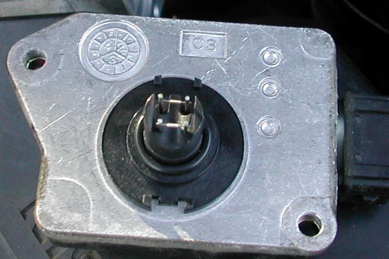
I get what your saying about not being able to use a different maf, but what about replacing those two wires (pictured below) on our stock maf (what are those by the way) with a slightly larger diameter wires? That would lower the resistance inside the maf itself. That way I'm not messing with the output I'm messing with the input the sensor is useing. Everything else that the maf does says the same. It just now thinks that more air is getting in. Which is correct because we would use a larger diameter maf housing. Either bore out a stock one or build one.
Credit goes to Precise for the picture
-
The vg30/33 doesn't make enough power to add a 6th gear at highway speeds.
Want better gas mileage get more efficient engine.
VQ35 with the tranny out of a 350z.
-
Our maf works by putting out x volts through the hot wire and measures what it gets back. Depending on how hot that wire is allowed to get will dictate the resistance and thus the mass of air moving through a known diameter pipe. If I want the computer to think less air is going through the housing I would add a resistor to the line making the computer think the hot wire is hotter than it is. And if I wanted the computer to think more air is getting into the engine I would reduce the amount of resistance.
So if my above statement is true then if we want to use a larger MAF housing(boring VG33 etc) then we need a way to reduce the resistance of the hot wire circuit by an amount proportional to how much larger our new housing is.
I think the ways to reduce resistance is to cool the conductor (not likely) shorten the circuit (also not so likely) or increase the size of the conductor. Since the copper wire that goes to and from the maf doesn't really bring a lot of resistance we would have to look at changing the hot wire in the maf in order to change its resistance.
So assuming everything I have just typed is correct what is that thing made out of and can we get a slightly larger one proportional to the size of our new maf housing.
I am sure after the crack wears off this will make absolutely no sense but right now it sounds good.
-
If you have disc on the rear, MY1PATH did a sweet trick I believe he made a write up on for flipping the cables to the top of the backing plate. As for the actual driveshafts, I can't recall anyone on here with any ammount of lift (with factory diffs of course. Swapped people dot apply) having issues with stock shafts.
Awesome So I can lift to my little hearts content.

I saw that write up and did it the next day. Way easy and super simple.
for anyone who later finds this page and is looking for that writeup
-
i think he meant the drive shaft that connects the trans/xcase to the rear diff? i dont think there are any issues with the factory drive shaft with a lifted pathy...I have 3" rear lift right now and the shaft length has barely changed, it's angle towards the x-member though might be of concern if your shocks are long enough, it may hit the x-member. I am going to modify a an upside U shape into the crossmember so the shaft can travel through it so to speak.
The only thing you really have to worry about is the tension on the e-brake cables. When you lift the rear (with longer shocks) and/or have a body lift you will break your cables if you don't extend them down further.
I am about to add another 1.5" of lift in the rear for a total of 4.5", so once I do that I'll let you know if I have to modify anything. I already made 3" drop brackets for the rear e-brake cables(they are super easy to make if you have a welder), but will probably extend them to around 5" since I have a 3" body lift but this will be based on your trucks setup.
If you were talking about the front cv joints then there aren't any longer ones that I know of but I am quite interested to know about the porsche 930 outer cvs? Do they travel further without binding or are they stronger?
You nailed it. Sorry about my poor grammar that's what I get for posting between service calls.
I'm interested to know more about that Porsche swap too.
Fuel injector wiring/connector repair (damn rats!)
in 90-95 WD21 Pathfinders
Posted · Edited by ejin4499
Its not a bad pull as long as your willing to take the upper manifold off. Its only 4 or 5 bolts and some hoses which you probably need to replace anyway. Everything on the top of your engine including your injectors goes back to that bunch of wires and connectors at the front of your engine. The only tricky one is the knock sensor which is under your lower intake but you can get your hand in there if your patient and don't mind the squeeze. Personally with all the rats you have described I'd take the intake down to the heads off so I could clean it all out and make sure they didn't leave you any more presents. Even with all that its easier than chasing down wires and plugs and heaven only knows what else, And I would seriously hate to be chasing a wiring problem that turned out to be a vacuum leak.
Here is a pic of the bugger with the lower intake out of the way. yes that is a vg33 but its close enough.