- Sign In Changes: You now need to sign in using the email address associated with your account, combined with your current password. Using your display name and password is no longer supported.
- If you are currently trying to register, are not receiving the validation email, and are using an Outlook, Hotmail or Yahoo domain email address, please change your email address to something other than those (or temporary email providers). These domains are known to have problems delivering emails from the community.

peejay
-
Posts
137 -
Joined
-
Last visited
-
Days Won
8
Content Type
Profiles
Forums
Calendar
Everything posted by peejay
-
Excellent info as always, everyone! When I was looking at spring clamps initially, I came across some aircraft-grade ones that have an "extra" smooth band on the inside to prevent digging into the hose. Of course, they came at aircraft-quality prices, so I bailed!
-
...and I've been trying to use the good (i.e. cost way more than I'd like!) worm clamps, when I do use them, to avoid this: (This probably was a constant tension clamp originally, and was replaced with a worm clamp sometime in its life).
-
Hey, that's what I did! Y'all make me feel like I might actually be doing things the right way sometimes!
-
Good point about the pressure, I didn't think about that! The transmission cooler lines use constant tension clamps, so that system must be much lower pressure than the power steering?
-
HELP!!! My engine started smoking and now it wont crank!!!
peejay replied to CobyGoertz's topic in 90-95 WD21 Pathfinders
Post a picture of the truck so we can convince you to keep it! -
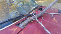
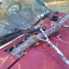
Okay, I overthought it (got some help from the GJ forum, too)... I think the "magic" is in the little washer at the tip of the screw, it's what does the pushing, but I still can't figure out how it does the pulling! At any rate, loosened the clamp, sprayed some WD40 on the hose to help ease it off and voila. Here's a pic of the loosened vs unloosened clamp, in case it comes up at a dinner party:
-
Been wanting to ask this for awhile, finally getting around to replacing water pump/timing belt, so figure now is a good "time"! How do you remove the tension on these wire hose clamps once the screw is loose? (while we're at it, how do they "work"? the design looks "backwards" to me, so must be my logic that's flawed!) Also, I'm thinking of replacing ALL the wire clamps with constant tension spring clamps, bad idea? I know serviceability/access for removal may be the greatest "con", but I plan on getting a good set of hose clamp removal pliers that should help with install/removal, when the time comes. Thanks!
-
Thanks for the update, and glad you're back in business!
-
Order New A/C compressor & 3 in a row have the wrong wiring
peejay replied to PamPoovey's topic in 90-95 WD21 Pathfinders
Just took a look at rockauto myself, you didn't by chance happen to order the Four Seasons one, did you? Looks like it has that "other" connector: -
Yes, everything start said! (I didn't know about the water passages/larger bore, I thought they just increased the stroke. For that much trouble, I'd just swap the entire engine.)
-
a - find a VG33 parts engine and use its cylinder heads (drill your exhaust manifolds to fit the larger studs) b - find a VG33 engine and use it, Frankenstein parts from your VG30 engine (crankshaft stuff) c - find a VG33 engine and swap it in (reuse your VG30 oil pan, have someone cut and braze the AC lines to mate the VG30 lines with the VG33 compressor) Plenty of good writeups around however you decide to proceed!
-
Crankshaft position sensor question
peejay replied to heavenjumper's topic in 90-95 WD21 Pathfinders
Excellent! (The FSM says to "replace the entire distributor assembly with camshaft position sensor if faulty", so you're on the right track!) Good luck, and keep us posted! -
Crankshaft position sensor question
peejay replied to heavenjumper's topic in 90-95 WD21 Pathfinders
Now, don't "quote" me on this, but I thought the crank angle/position sensor didn't appear on the Pathfinder until the VG33 engine ('96 and later) as part of OBD-II emissions? Have you downloaded the FSM? The Haynes is good for better explanations of things once you know the problem, but the FSM is more detailed at helping track down the problem first. -
Crankshaft position sensor question
peejay replied to heavenjumper's topic in 90-95 WD21 Pathfinders
Could you mean the camshaft position sensor (located in/part of the distributor) as I don't think these models have a crankshaft position sensor. Also, a fuel pressure check may be another good thing to verify/rule out. -
I love it when a plan comes together! Glad it was something simple, and that you have the wherewithal to get the timing belt done now!
-
That sucks, and is the kinda "freak" occurrence that would make me wanna swap in the VG33 engine, but that comes with it's own cans of worms, too! (Go for it if you can easily get a replacement engine!) And you've probably already seen this thread?
-
Ditto on that. "Easy button" is disconnect the fuel supply hose from the rail and place the end in a fuel container, pull the fuel pump relay, and run 12V straight to terminal 5 to let the fuel pump do the work for you. Be sure to go back with a new fuel filter, too.
-
Excellent info as always, slart, thank you!
-
KNOW that the valve cover gaskets are leaking?
peejay replied to peejay's topic in 90-95 WD21 Pathfinders
Well, got the passenger's side valve cover installed, thanks for all you all's help! Ran out of time, so I'll hafta test it tomorrow, if all is well, I'll move on to the driver's side. Special thanks to slart, whom I "questioned", about the grommets expanding to fill the cup washers. How did you all know that they do expand, and I didn't? Well, admittedly, the first time I replaced the gaskets, I did not replace the grommets--I didn't even know they were a replaceable thing! Live and learn! (Oh, I recommend giving the good folks at belmetric a holler for your fastener needs, their customer service was top notch in helping me find the hardware I wanted!) -
Slart, would you mind demystifying the knock sensor operation? It was my understanding that when the sensor senses knock (for whatever "normal" reasons), the sensor sends a signal to the ECU to retard the timing to eliminate the knock. Does this scenario always produce a code/check engine light, letting the driver know that "uh-oh, something is causing knock, better check it out"? Or is the system "supposed" to only trigger a code/light if there is an issue with the knock sensor/circuit? Thanks!
-
(Since the fuel gauge came up as part of this thread...) For those of us experiencing problems with the fuel gauge (not reading, reading intermittently), do you all recommend to start troubleshooting with the sending unit or the instrument cluster/gauge itself?
-
Agree with Frenchy, the factory service manual will prove invaluable (you "might" be able to find a copy online, post back here if you can't). In the meantime: 12 = Mass air flow sensor circuit 21 = Ignition signal circuit 34 = Knock sensor circuit 51 = Injector circuit For the 34/knock sensor circuit, if the knock sensor is in fact faulty, I would recommend relocating it to the top of the intake manifold so that future service/diagnostics are easier. (It's buried underneath the intake manifold and is a pain to get to). There are lots of discussions/writeups detailing how to relocate it.
-
KNOW that the valve cover gaskets are leaking?
peejay replied to peejay's topic in 90-95 WD21 Pathfinders
Alright, just about ready to go back on with the gasket, but which side goes toward the cylinder head, flat side or "round" side? Here's a pic the first time I did it, looks like I had the round side toward the cylinder head, but now I'm questioning myself...thanks! (Update) It appears there is only one way the gasket(s) can go on, round side down (toward the cylinder head), who knew! (Y'all did!) -
KNOW that the valve cover gaskets are leaking?
peejay replied to peejay's topic in 90-95 WD21 Pathfinders
I'm going through the hassle of removing the RTV (that I put on previously) right now, won't be doing that again! -
No torque converter lock up? Did you thank your lucky stars???
