- Sign In Changes: You now need to sign in using the email address associated with your account, combined with your current password. Using your display name and password is no longer supported.
- If you are currently trying to register, are not receiving the validation email, and are using an Outlook, Hotmail or Yahoo domain email address, please change your email address to something other than those (or temporary email providers). These domains are known to have problems delivering emails from the community.
Leaderboard

Popular Content
Showing content with the highest reputation on 03/12/2025 in Posts
-
I'm honestly not sure when ABS started in these, and whether it was a trim thing or a federal thing. The part numbers for the ABS valve block go back to '90, but it's not in the '90 manual. If yours has it, the valve block is under the truck, on the inside of the passenger's side frame rail, sorta under the passenger's seat area IIRC. Should be an aluminum casting with a bleeder, an electrical plug, and two brake lines going into it. The control computer for mine was under the driver's seat, but IIRC '92 (and earlier?) had it under the stereo. The sensor reads from the pinion flange on the rear axle. If yours doesn't have it, you're not missing much. All it does is release the rear brakes if it sees them lock up. There's no pulse action, no pump, no improved stopping distance. It's just trying to stop the rear end from stepping out and potentially rolling the truck. I guess if road conditions are bad enough to allow the rear brakes to lock, and the driver doesn't know to pump the pedal to regain control, then it's safer to nerf the rears, keep it straight, and take the hit in the crumple zone.1 point
-
The harness adapters finally arrived...I'll (hopefully) connect them tomorrow and post an update/pics.1 point
-
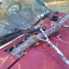
Alright, bit of an update... First off, I did not meet my goal of having it rolling by the end of Feb. Maybe this weekend, we'll see. Right now, the axle has been removed from the truck for hopefully the last time. Pulled it off to finish welding the bump stop pads, steering stabilizer mount, whatever touch-ups, and then paint. To that extent, axle work is DONE! Will get some pics when it's daylight. The last couple weeks have been super busy. Almost every day and/or night that I can. Updates... Finished the air conversion for the sway bar disconnect. Big thanks again to @TowndawgR50 for making the piston rod and all his support on this project! Have yet to test it on the truck (my OBA setup has been pulled for re-work) but it's ready to go. Not sure I showed this previously, but I made it so that I don't have to pull parts from the engine bay to access the strut tower/mount hardware any more. Now I can just unbolt the upper coilover mount from underneath. Maybe one day I'll pursue a strut tower brace. Finished the brake caliper mounts! Well...almost. Still need to powder coat the RH side, but the LH side is done. This f$kc!ng pic just reminded me right now that I forgot to grind the knuckle for clearance to install the lower caliper bolt, which I needed to switch out to socket bolts due to the space. Well, guess that's happening tomorrow and some repainting... ... I did have a bit of a setback with the power steering setup. I was mocking up the steering stabilizer and had the truck running with the wife turning the wheel so I could change for clearances. *SPLOOSH* ATF spraying all over. The aftermath... After assessing the failure, I deemed it operator error on two faults: Despite being as gentle as I could to push the braided sheathing back using a small screwdriver per instructions, I must've weakened the PTFE liner enough. I must've pushed the braids too far back with insufficient overlap on the ferrule. So, I can tell you that ATF absolutely sucks to clean up. It is a nasty, nasty chemical. (And for those wondering, yes, I am using ATF as my power steering fluid...it's what is spec'd.) That $hit got everywhere. I cleared the space out and power washed the engine and concrete shortly after this happened and the engine is still dropping ATF in spots...and I only worsened the mess during the repair process. I can't wait to get the truck out of the garage to really hose it down! Anyway, I ponied up for a proper tool from JEGS that pushes the braid down uniformly and to the correct depth. I was reluctant to drop $50 initially, but I paid the price and then some for not getting it in the first place. I pulled all the lines (two; four fittings total) to inspect and redo them. My original fitting installs were showing a little bit of fatigue that likely would've let to failure again. I have a little more confidence this time around having used the tool. Here's the new line, shown on the concrete where the spill occurred as indicated by the silhouette where my foam mat was. This was the direction the steering stabilizer was heading before the busted line: After doing all the other work on steering angles and such, this is basically the only place I had left to mount it. It hangs about as low as the axle tube, so it's not really eating any more ground clearance, but it will likely be the first thing to be struck. I tried to keep the brackets simple, and while this piece worked great, the plate came too close to the diff cover for my liking. I went with a different design that rotates the plate around (the u-bolts have plenty of clearance) and allows me to slide the bracket a couple inches towards the passenger side just in case. Pics to follow. ... I received my front driveshaft! Ebay special for $300, custom length for my project, intended for "hack-n-tap" Jeep applications where they do a slip-yoke eliminator (SYE). Double-cardan unit with a probably generic Spicer 211229X/Neapco N2-83-388X flange and uses Spicer 1310 series u-joints. The TX10 flange is equivalent to Spicer 2-2-1309. They're fairly similar, dimensionally, but an adapter is needed. I fired up my CNC router to make a mock-up adapter based on Nissan Nut's version. He pockets one side to hide the hardware used to attach it to the TX10, and then has threaded holes bolts to attach the Spicer flange to it. I eventually realized either it's not a good design, or I still can't understand half the stuff he writes. Probably both. There's not really a good way to get a wrench on those bolts. Use of socket bolts wouldn't be much easier. (I came up with what I think is a better design, discussed below.) As far as clearances go, this should do nicely! Clearance over my crossmember is perfect. At full compression, there's "enough" clearance under the sway bar. This is what full compression would look like (I didn't have the bump stop pads welded on, but you can see I'm nearly maxed on the coilover), but I will be limiting compression beyond what is shown in this pic, so my max compression will be less than this. After confirming the driveshaft fitment and clearance is good, I went back to thinking about the adapter and bastardized my v1 to make it v2: This actually uses rear wheel studs for the truck and the leftover axle shaft studs from when I did the disc brake swap. The lengths on these not only end up being perfect, but they're the same size and thread as the OE hardware for both the TX10 flange and the H233B flange, so I've got new OE hardware on order to replace everything (I still need to pull the rear diff to swap gears). This adapter will be 3/4" thick, with 1/4" pockets for the stud heads. Master TownDawg will be producing the finished piece from aluminum, since neither of us are convinced redwood is a suitable material. And unrelated to the SAS, I bought new terminals and really like them. I made something similar using replacement lugs and terminals, but this is way cleaner and better for some of the stuff I need terminals for. Ok, that's it for now. Getting closer to having it back to being on the ground.1 point