

Adam
-
Posts
333 -
Joined
-
Last visited
Content Type
Profiles
Forums
Calendar
Posts posted by Adam
-
-
One other note for anyone in the future who may go the Megasquirt route, there isn't an input for the knock sensor on either the MS3 or MS3X harness. You can use a spare input on the cable or you can use an input on the MS3 board. I chose a spare input on the MS3 board, I'll be using the JS4 input, it's directly under the CPU socket and you just solder a wire directly to it underneath the board.
-
Coolant temp sensor readings are as follows:
75F 2000ohm
85F 1750ohm
95F 1400ohm
105F 1300ohm
115F 1200ohm
125F 1000ohm
135F 800ohm
145F 700ohm
155F 600ohm
165F 500ohm
175F 450ohm
185F 400ohm
195F 350ohm
205F 250ohm
210F 200ohm
The water stopped gaining temperature right around 210 no matter how much salt I added but 210 is just fine.
-
Figured out the coolant temp sensor, one side definitely excites it and it reads off the other side. The green/red strip wire is the one responsible for supplying power. I'll be looking at the harness to figure out which one specifically it is tomorrow. Tonight I'll be making a chart for the coolant temp sensor resistance all the way from room temp to boiling.
-
Here's where it sits now. I'll be building a cable for the sequential injection part of this as well. If anyone knows the answer to my coolant sensor question let me know... I've looked through the FSM but can't find the answer... If need be I'll pull out my multimeter and check it myself...
Oh, and if anyone knows which wire on the plug goes to the outer ring optical sensor for the crank sensor... I don't need the inner one.
-
So looking at the diagram I've got some questions.
The coolant temperature sensor has 2 outputs on the Pathfinder ECU, what gives? Is one a 12V source and the other the one that actually reads the resistance?
Is pin 19 to the O2 sensor the O2 sensor heater circuit? I'd assume so based on the drawing.
-
Wired the injectors:
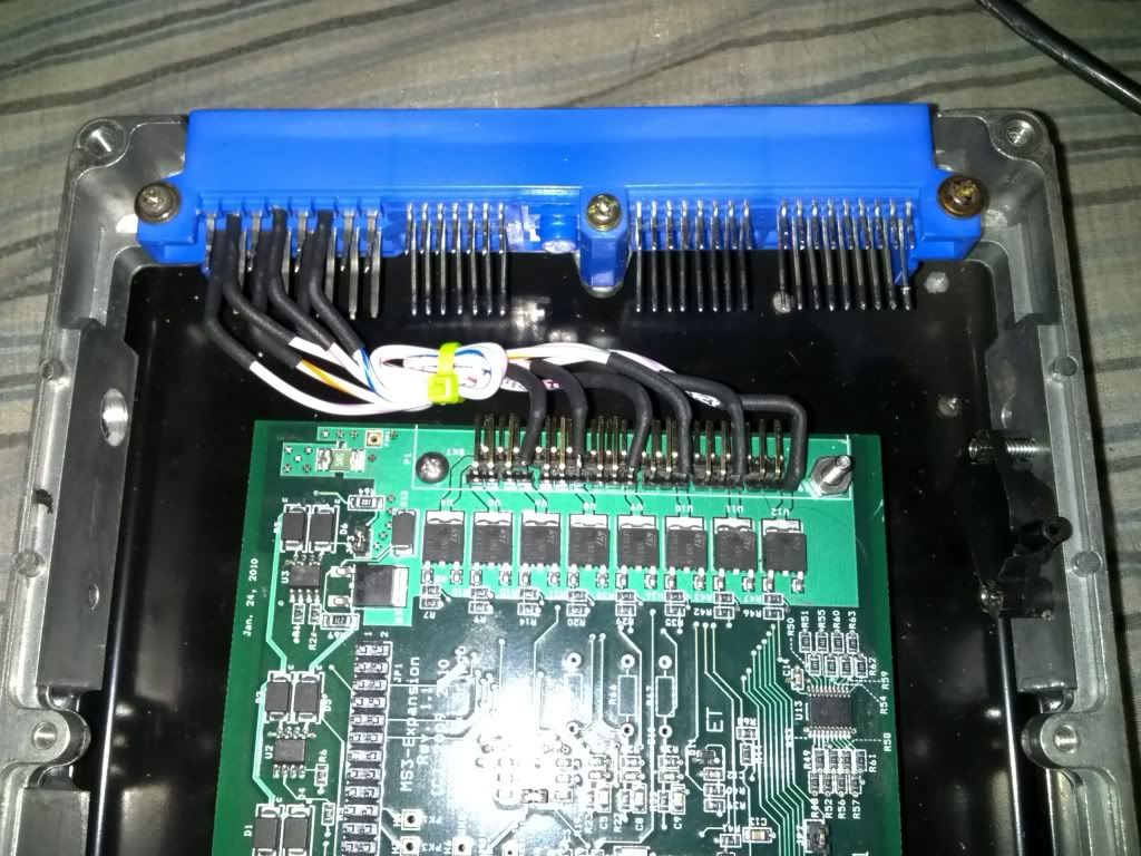
The Pathfinder's firing order is 1-2-3-4-5-6 so this part is simple. On the Megasquirt you wire the injectors in the order they fire, since they fire sequentially you wire A to 1, B to 2, etc etc... The Megasquirt information tells you all this but it helps to have it all in the thread.
-
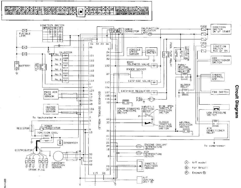
Put the ECU pinout diagram and the wiring to pin diagram on a single image file for quick reference... Don't like how the FSM has it (especially since I have the FSM in PDF format)...
-
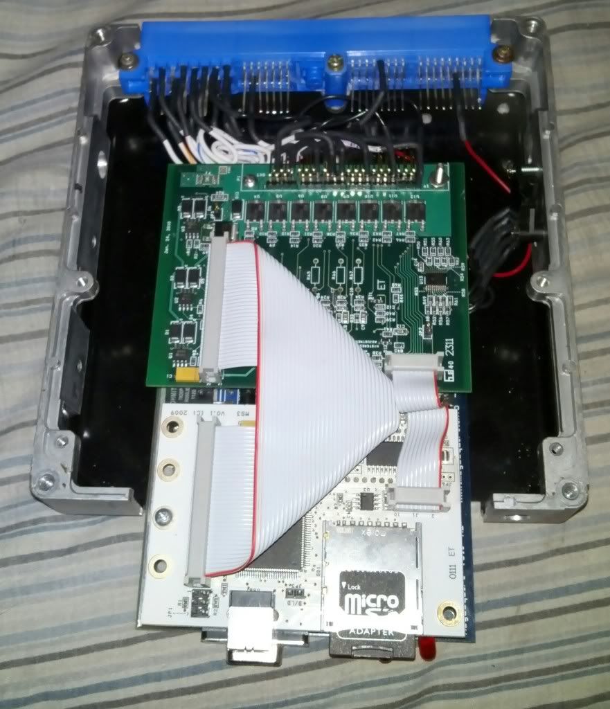
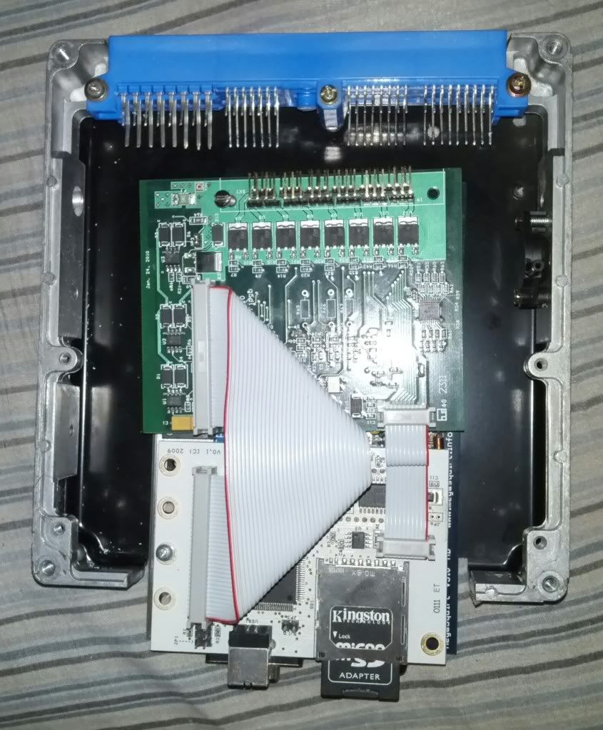
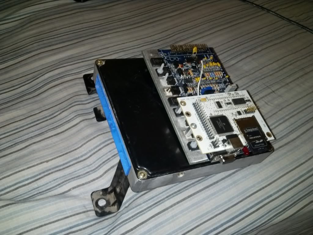
Mounted the MS3X in the Pathfinder ECU at its final location:
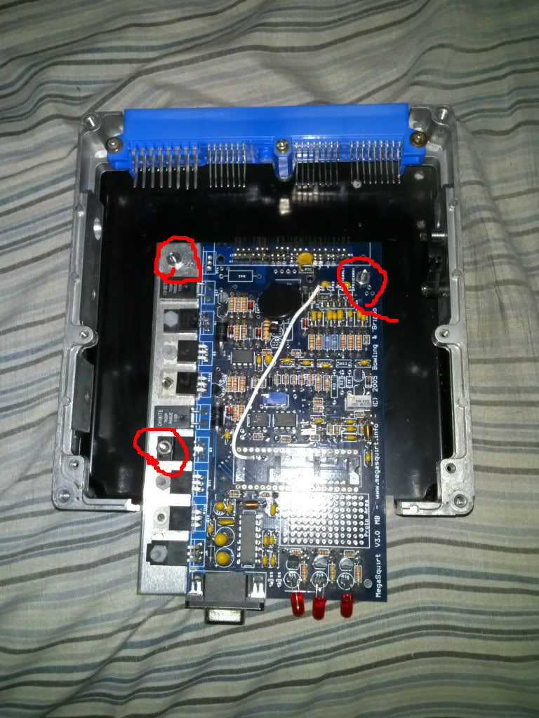
The 3 red squiggles are the 3 mount points, the board is suspended above the sheet metal bottom by a screw and a nut.
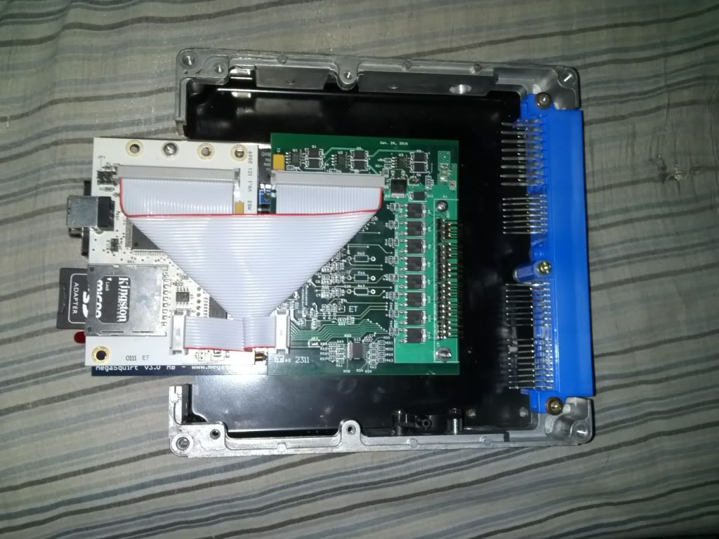
Here's everything completely mounted, all add-on boards. Time to start the wiring!
-
i have a few times made cases for my own electronics. if you had access to a small break or even if you are handy with some sheet metal benders you could quite easilly make a cap with some mounting tabs with holes drilled in them out of sheet metal. drill a couple holes on the flat surface near the edge of the hole you cut in the stock ecu casing and tap them for some uber small computer screws. i can envision it right now.
That's definitely something I'm considering.
-
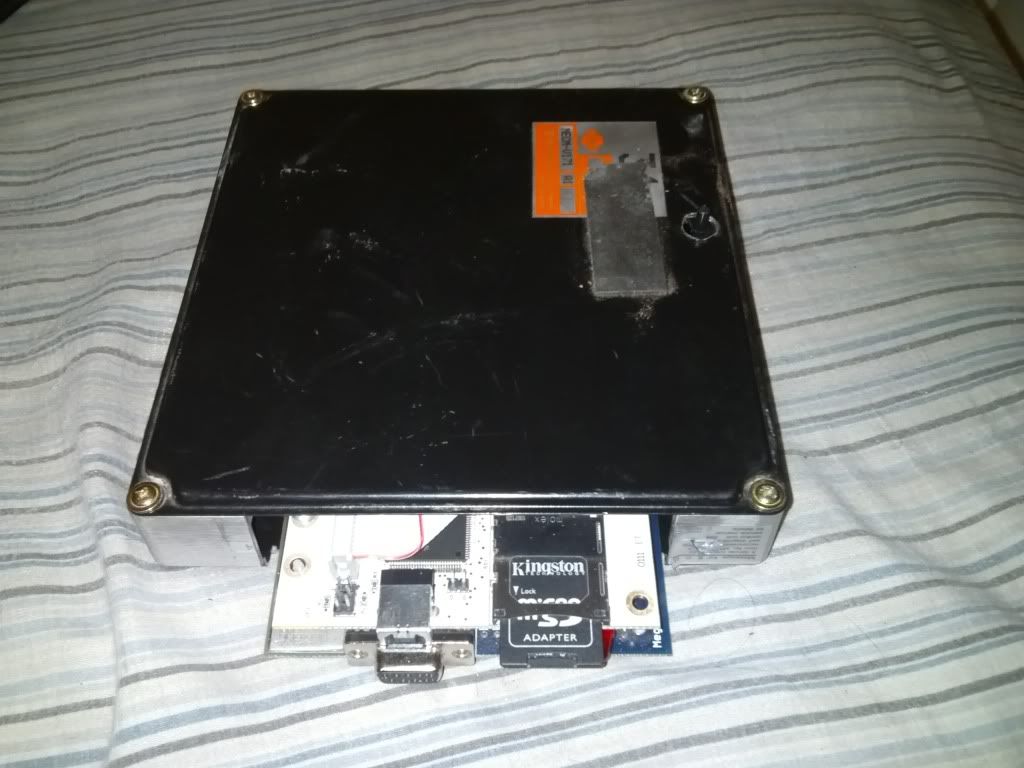
Been hacking away at the stock ECU housing getting things situated. Here's where I'm at:
You can see I've moved the MAP sensor to the side of the ECU housing, the barb for it will stick out the top of the ECU, it wasn't in a very good place under the board (stock location for the MS3X if you use the case supplied by DIYAutoTune).
I'm not 100% sure how I'm going to approach the back half of the case so it's not just wide open... Jury is still out on that.
Here it is with the cover on, you can see the MAP sensor hanging out:
-
Well, initial findings aren't great. The USB port makes the MS3X board too tall to fit in the short casing of the Pathfinder ECU. Still considering options.
-
Didn't check the mail until just now, got me spare ECU in!!!
It's gonna be a tight fit, if it even fits. I may have to open it up on each side and make cover plates.
This is the orientation I'd like to put the Megasquirt in inside the case. We'll see how possible this is to achieve.
-
I paid for a shop to do one of my rear's on my Pathfinder, think I paid $250 total but that was also because he had to recondition the axle since the bearing really busted up and kind of damaged things. He did great work though, it was well worth my money. I've done wheel bearings on my BMW's but they're nothing like the Pathfinder IMO, I'd rather do them all day long...
-
LOL
20 miles and an hour or more drive.....Nevada, Tx is right next to BFE, Tx....
I need to go there anyways, there's an AC compressor at that boneyard

Replaced the DB connectors with pins that I can solder wires directly to easily and shrink wrap for added support.
-
Just realized the Stanza TB is 20mi away....
-
It all depends on the usage scenario I guess. MAF responds better to small modifications without needing a tune again while MAP seems to be more reliable and easier to deal with as long as nothing is changed.
Not really a concern with the Megasquirt and VE Analyzer...
-
however you can hurt the top end power because of the obvious flow restriction that MAF sensors can have.
Hence why I feel MAP is superior

-
Yeah I'm not too concerned about boring the manifold, that will be pretty easy.
-
We had a couple in my local Pick N Pull last time out. I'm going out today so I'll check again. Sounds like a fun project!
Awesome, if you find one shoot me a pm.
-
240sx KA24DE throttle body is also 60MM and bolts right on (minus boring the manifold) and the TPS isn't upside down either. Put one on mine a few weeks ago, made it pretty snappy.
Yeah I looked at those as well but they were generally more expensive

-
N/A tunes are not as critical as FI tunes, but if you are going to change out the size of the MAF housing, it may be a good idea to at least chat with a local tuner. You said money is tight, but tuning on trial by error can end up rather spendy.
As far as getting a baseline dyno, absolutely. Not just for HP # but also your AF ratios, that will give a lot of insight to where gains may be made. I've been curious as to tuning options for this engine, so I will be following this thread with interest.
Do have a chat with a tuner, they are car nerds just like the rest of us and must do want to help!
You're not up to speed on what I'm doing or what VE Analyzer is. There is not going to be a MAF, at all. It will be MAP (Manifold Absolute Pressure) sensor based, it's a much better system than a MAF. There also is no trial/error to this, VE Analyzer is proven technology. A/F ratios will be picked up by my wideband O2 sensor (meaning they will be very accurate) and datalogged. The dyno tuning will literally be just fine tuning once VE Analyzer goes through a few datalogging sessions. VE Analyzer tunes based on O2 sensor, knock sensor, and any other readings it picks up from the engine.
My friend, who I linked earlier (and lives in WA), has ONLY done VE Analyzer with his BMW (using the same engine I'm putting into my old Bimmer), and he took it to the dyno to see where he was at:
http://m54megasquirt...04/to-dyno.html
He's about 40hp to the wheels higher than stock (he has some mods) and about 10hp higher than his previous solution which was a modified BMW ECU with a performance chip.
-
Looks like a big project, good luck. I might add that the Restrictive MAF is kind of pathfinder specific. The n60 MAF I am running with the M30 ECU is over 75mm on the inside and only has a tiny probe hanging down to take the air reading.
As far as the TB goes, the KA24 TB found in a Nissan Stanza is 60mm vs the stock 54mm for pathfinder. In stock form the 54mm TB yeilds no restriction as a a vacuum gauge reads 0 (zero) at WOT reline. 60mm will feel more responsive but the linkage and TPS are on opposite sides. You can run it upside down or you can install the pathfinder linkage and TPS on it. The bolt pattern is the same and both TB's are actually machined from the same casting. ones, just bored out a little bigger and the Spring post is pressed in at a different spot.
Thanks for the info!
Would the Stanza throttle body be one of the 60mm's? I'm assuming so since it's KA24... Looking at this:
http://www.ebay.com/itm/90-91-92-NISSAN-STANZA-THROTTLE-BODY-W-CRUISE-CONT-/250959451960
Would obviously need cleaning up!
-
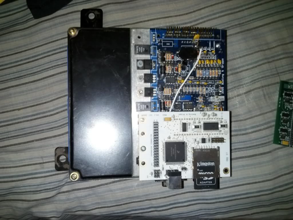
I went ahead and pulled the DB connectors off the Megasquirt boards so I can directly wire them when the OEM ECU gets here.
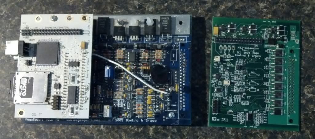
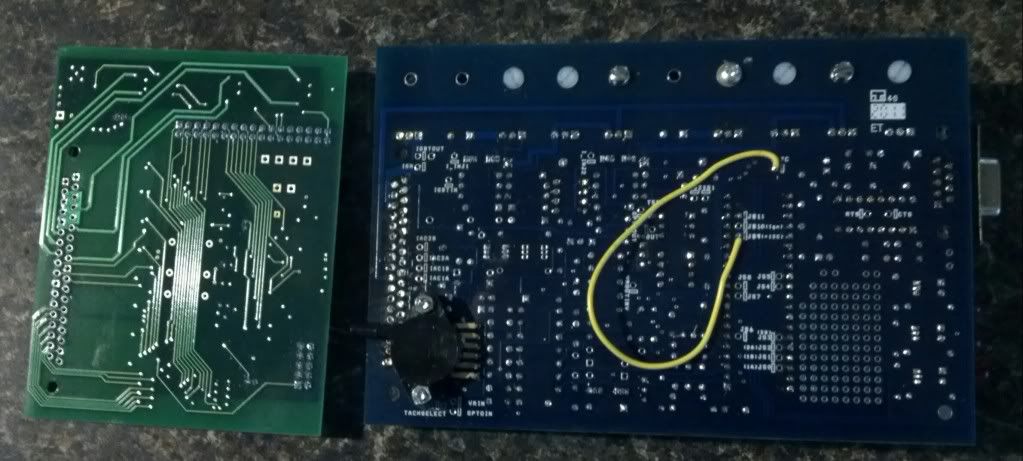
The round black thing on the underside shot with the tube sticking off is the MAP sensor. I'll be relocating my ECU to the glove box while I'm at it which will make it easy for me to get the vacuum line for the MAP sensor plumbed... Not sure exactly where I'll pull the vacuum source, I may split it off the vacuum line for the fuel pressure regulator.
Need to pick up a better barometer as well so it can compensate for weather even better. A friend of mine talks about that here.
-
My LS1/2 upgrade coils will be shipping Monday

Megasquirting my WD21
in The Garage
Posted
Got my coils, wideband and crank sensor replacement plate (under the wideband, oops) It's like Christmas
  I'm going to try to get it to start tonight, if I do I'll immediately do some datalogging and try to get a decent tune with VE Analyzer.