Leaderboard

Popular Content
Showing content with the highest reputation since 04/29/2024 in Posts
-
Ditto on that. "Easy button" is disconnect the fuel supply hose from the rail and place the end in a fuel container, pull the fuel pump relay, and run 12V straight to terminal 5 to let the fuel pump do the work for you. Be sure to go back with a new fuel filter, too.1 point
-
Well, got the passenger's side valve cover installed, thanks for all you all's help! Ran out of time, so I'll hafta test it tomorrow, if all is well, I'll move on to the driver's side. Special thanks to slart, whom I "questioned", about the grommets expanding to fill the cup washers. How did you all know that they do expand, and I didn't? Well, admittedly, the first time I replaced the gaskets, I did not replace the grommets--I didn't even know they were a replaceable thing! Live and learn! (Oh, I recommend giving the good folks at belmetric a holler for your fastener needs, their customer service was top notch in helping me find the hardware I wanted!)1 point
-
Agree with Frenchy, the factory service manual will prove invaluable (you "might" be able to find a copy online, post back here if you can't). In the meantime: 12 = Mass air flow sensor circuit 21 = Ignition signal circuit 34 = Knock sensor circuit 51 = Injector circuit For the 34/knock sensor circuit, if the knock sensor is in fact faulty, I would recommend relocating it to the top of the intake manifold so that future service/diagnostics are easier. (It's buried underneath the intake manifold and is a pain to get to). There are lots of discussions/writeups detailing how to relocate it.1 point
-
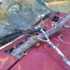
Progress has been very slow. Kids' sports in full swing and I started a new job at the beginning of April. New focus had been getting my Frontier back into commuter mode. I'm dropping off a set of LE wheels for refinishing and powder coating in the morning, and new rubber by the end of the week. It should look fantastic...it better be for what I'll be paying. Since last update, I built a new bracket and re-slung the engine. I didn't like that I could only use one bolt on it due to space limitations, but it creates a cantilever that holds fine. The intermediate piece is bar stock from the WJ steering shaft after I cut it down. View from the bottom... Engine hasn't fallen to the floor yet, so it must be good enough. I also mulled considerably on the radius arm brackets. Wanted to get caster adjustment since the optimal angle varies depending on who you ask. OE caster is 3°±0.75°, but the straight axle community says 4°-8°. So, I'm targeting 5°, and the caster adjustment I did gives me ±2° range. The final brackets... My craptastic welding. Old Blue in the background to distract you. And finally, actual results... Finding the right caster (or really, camber bolts turned 90°) was a pain. The front FJ bushings use 16mm bolts, and the only 16mm caster/camber bolts I could find were the lobe style we use for camber adjustment on our struts, but they were all just a little too short. Anything else I could find that used a cam washer was 14mm and too long, except ones for a late-80's to early-00's GMC/Chevy trucks and vans which were a good length but still 14mm bolts. I ended up using 14mm ID x 16mm OD sleeve bushings to fill the void. Took some effort to get the slotting sorted to make the adjustment work, but they work great. Other hardware being used is OE Toyota. I did not do a very good job of maintaining spacing on the brackets for the bushings. I had scrap bushings from a prior job to swapping out bushings on FJ arms, and used them as spacers, but the welding still tightened up on them. I was able to coax them to width without angling them out, except for the lower panhard mount. Just needed to grind down the sleeve for a few seconds and it's good to go, though.1 point