

andrewt6447
-
Posts
79 -
Joined
-
Last visited
Content Type
Profiles
Forums
Calendar
Posts posted by andrewt6447
-
-
Are you happy with them?
Yeh man, well happy.
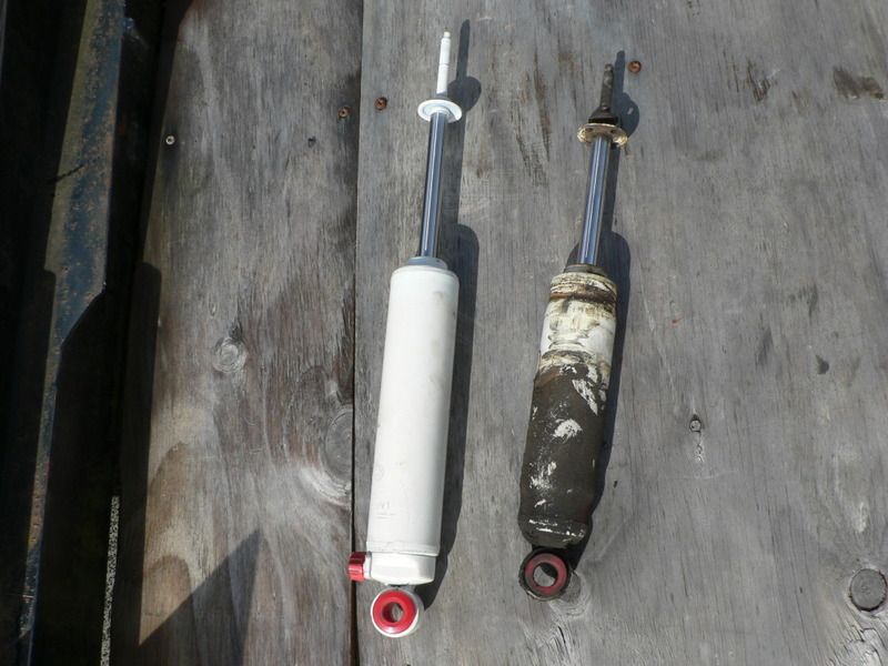
I use the rs999202 adjustables, which I really recommend over the non adjustable 5000. The local supplier doesn't do the 112's...but looking at the spec they are a couple of inches longer extended, so probably better.
I used 999136 in the front, the 214 didn't have enough extended length for me.
I had a set of 5000 series in it for 10+ years with no issues, so I'm well sold on the quality of them....
-
I used Patrol spec Rancho with different bushes on mine.
-
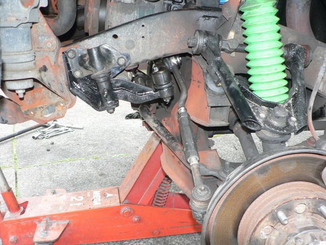
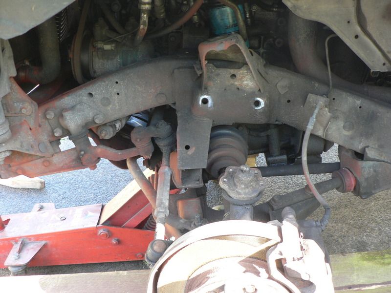
The shocks that were in it were limiting the travel. I'd already extended the upper pin to allow a bit more extension, but with the new arms it needed a fair bit more. I was hoping for a bit more than I got.....
The cv boots are well shot, it need new ones, but they aren't why it's binding at full extension, it's simply because the cv's can't take any more angle....
As for the shock bottoming, I'm not real worried, it will take a fair bit of force to compress the bottom bumpstops that far, and the shock mounting bushes have some give too.... or the first time I launch it properly it'll bust something

On the cv boot subject, anyone know of something better/tougher than stock or standard replacement rubber one's?
-
Done the rest today, 2wd stuff in there now. And I put my prototype (it was the first one I made...changed the design a little now...) idler brace, and a bit of reinforcing on the arm too. Should be all sweet now. The outer tre's still are pretty much at their max angle, and the adjusters collide with the swaybar at full lock/extension. But not too badly. Machining the adjusters was easy as, took about 1/2 hour to bore and re-tap both adjusters and the locknuts.
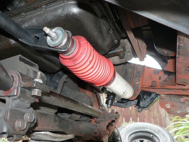
And the mount for the damper....
-
Did that on my mates one....same as nunya, jack and a bit of wood sorted it....
-
We pay for deisel mileage here so my '90's done about 10,000k's since iv'e owned it
 (13 years) about 109,000km on the clock
-
How do you extend the steering shaft? I have the lift installed I just need to hook the steering shaft back up and I cant get it to extend. Ive tried using a hammer and nothing. The shaft should extend without loosening the upper bolt right?
Mine reached, I loosened the bolt and slid the knuckle to the end (the bolt will stop you going too far), and the extension bit took up the rest.
-
I guess mine doesn't count as a 'clunker', it's a much newer '90 model

The old beast does everything I want, and for the life of me I can't find anything better . All the new stuff is either too big (Patrol/safari and Cruiser) and/or just too piss weak. There's no way the newer stuff would take what mine's been through....
-
I like your front clip exo-skeleton, but you mught want to improve that rear mount, I'm not sure the running boards are sufficient.
B
Lol, yeh, they've survived 'till now, but some proper sliders are in the planning.....
-
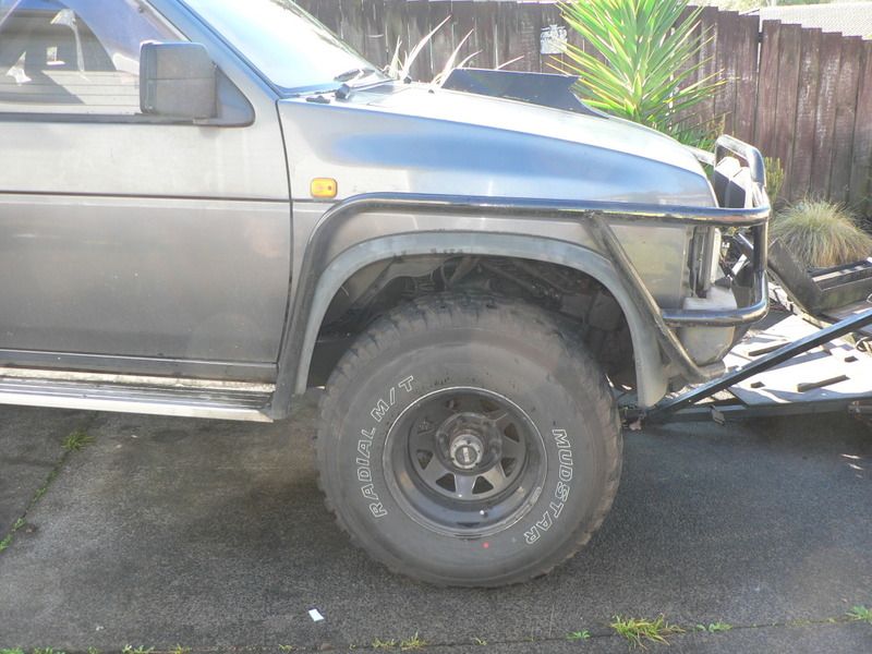
Everyone is probably sick of these, but I'm gonna annoy ya all with it anyhoo......
Before
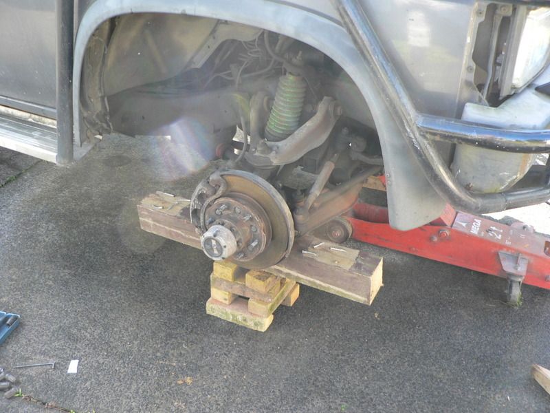
mMake sure your bricks/timber are load rated for a Terrano...
Add this;
And these
And slightly longer...
And you end up here...
I'll explore if there's any more Height to be had once I go back to work next week. I don't think so tho, there's only an extra 15mm droop over the old setup I had. I had to add a 10mm spacer under the bumpstops or the CV's bound. The shocks are right on the limit lengthwise, they will bottom around 10mm after the bumpstops are contacted.
I may also explore lowering the front diff a bit.
Otherwise that sas option is always there......
-
 1
1
-
-
Right, I've found the answer....at 640mm from the steel gaurd lip to the center of the hub, the CV's are starting to bind. That's only 15mm more than I had with the shock/bumpstop mods I had already. If you keep going they bind and stop any more travel. Everything else seems to be ok.
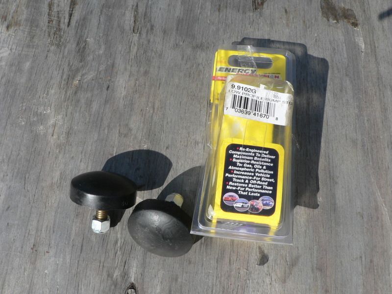
I'm also going to suggest staying with stock arms with low profile upper bumpstops and slightly longer shocks, unless you wanna spend big bucks.
-
Now you mention it, that would probably be the easiest way to go, just chop the whole end off drop it 1 1/2 " then weld it back on and gusset the sh*t out of it. The angle from the pivot to the bj should be re-adjusted to 10deg from flat and add the extra length too.
I was initially thinking of cutting the arm halfway and angling the rest of it down so it made a ~ shape.....
I'm now thinking cut it right where the V meets, weld on a 3" deep peice of 1/4" flat flush with the top of the arm so it protrudes around 1 1/2" below, weld the end bit back on flush with the bottom of this plate, but re-angled. Then you could weld a triangle shape bit of 1 1/2 X 1 1/2 " rhs (around the same size as the arm) that angles back from the bottom of the plate to the bumpstop pad, and a couple of decent gussets on top of the bj pad back to the top of that plate. Sound easy enough?
-
Check your upper ball joint, upper control arm, UCA bushings and the bolts holding the UCA on. It's quick and easy, so do it before anything comes completely loose and does real damage.
X2. Sounds like the bolts are falling out/broken. It may be part of the brake problem too, the hose may be getting stretched/squashed with all the extra movement that's going on.
-
On the other side of the planet so you have to allow for different gravity and the fact you guys are up the other way, I get 525mm on the lower ( 20.7" or just a smidge over 20 11/16") and 272.5mm upper (10.7" or just a smidge over 10 11/16")
Measured with a tape/steel rule also, so there may be a tiny discrepancy in the actual measurements.
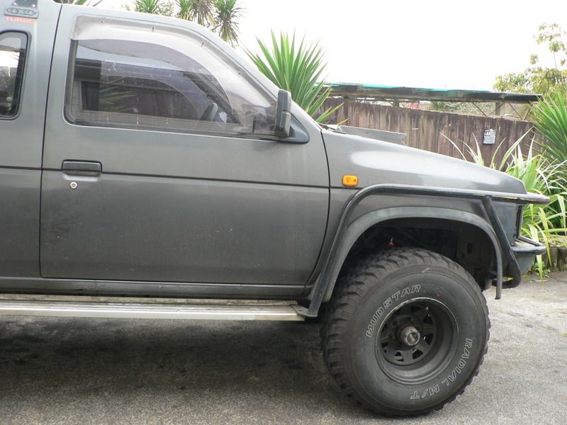
'90 D21 with cast lower/tube upper arms.
-
I've had the same set of rs5000's on mine (D21) for 13 years, and they're still going strong. I'm about to change them to 9000's (longer...) so I'm hoping for similar performance.
-
If you get the end of the arm down 1 1/2" it'll give you 3" of extra travel without changing the bumpstop pads at all. The stock pad is pretty flush already...
-
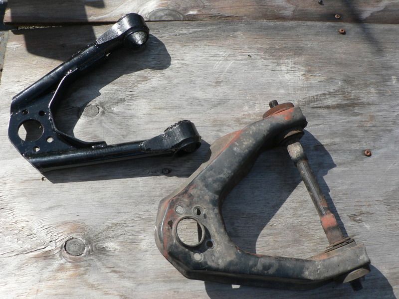
I've just made up a jig and made some new upper arms myself.
1 thing became apparent when doing all the measurements etc, the angle of the top BJ doesn't affect the alignment at all, and it won't tolerate more angle than the 10 (from memory...I'll hafta check) deg it is at already. In fact it gets lots more angle at full compression than at full extension, even allowing for an extra 3" droop. Don't increase the balljoint angle!
To get the correct alignment at 3" lift, the arms need to be around 12mm (1/2") longer than stock.
If I was doing it, I'd cut through the top of the arm just outside of the bumpstop pad, bend it down, then cut it just short of the bj mounting area at the bottom of the arm and bend it back up to correct the angle, which should also effectively lengthen the arm. Fill all the gaps with a bit of 3mm plate or something and give it a go.
-
I know, it's been done to death, but what I want to know is when does stuff like the cv's and bj's etc start to limit it?
UCA's sort the bumpstop clearance out, but what is the next thing to limit lift? Anyone know how much extra extension over stock is safe before cv's start exploding? I'm making some uca's and want to know how stupid I can go with them....
Sas may come later, jeep etc diffs aren't that plentiful over here....or at least good ones...
-
16.5mm instead of 18mm?

Yes, this is the correct size drill for an 18X1.5mm thread
-
you could always try buying an 18mm drill bit and a 18mm tap
Just in case no-one picked up on it, you actually need a 16.5mm drill

-
that is awesome! what drivetrain are you running to make the passenger drop diff work?
Lol, drivers side over here!
Have a look here... http://www.nissanpat...om-new-zealand/
and here http://www.offroadex...hp?f=18&t=27407
Nice work Pete!
-
Are those seats recliners? Mines a 2 door....
-
Warm the paint up before ya apply it. That helps too. Put the can in some hot water for a while (crack the lid first....).
-
You have to bore too much material out on the rim to make them to fit the 4x4 hub and is very unsafe to me. They would look good on a pathy but not safe.
Na, we do that stuff at work all the time. Still plenty of meat there when ya bore 'em for a Pathy.
Our factory alloy wheels are 10p offset (d21), so 35p would mean a 25mm spacer to get it spot on.
round dash relacement searched already
in The Garage
Posted · Edited by andrewt6447
No, You've got it backwards, the steering column is on the wrong side