

fleurys
-
Posts
2,169 -
Joined
-
Last visited
-
Days Won
48
Content Type
Profiles
Forums
Calendar
Posts posted by fleurys
-
-
17 hours ago, Zraver said:
Thank God for 2 things right now. One the search feature finding this post, two you providing all the part numbers and detailed pics. Saved me a bunch of trial and error. Thank you.
Cheers !
-
 1
1
-
-
wow !... This was some of my early ones.... This is great ! Looks like you wheeled your truck to places I used to go too !... Great pics !
S.
-
39 minutes ago, Inyourface1650 said:
I find it really interesting that they didn't make skids for R50 - it was sold and used in the bush for multiple countries - maybe just not the US?
Do the sfcreations skids have oil changing access holes for the engine, trans,and transfer? that's a must for me.....most auto shops will lose/screw up anything that has to come off. My front plastic air dam only has two bolts holding it in hehNo we do not have them anymore. We used to have them in my first versions of the plates, but most customers were not willing to pay for the work involved.
Cheers.
S.
-
Welcome !
-
 1
1
-
-
bank 1 is passenger, bank 2 driver. sensor 1 is before cat, sensor 2 after.
I recently did both sensor 1 on my 2003. The driver side one is easy to do as you can easily see and touch it from the engine bay. The passenger side is simply a matter of luck in my opinion... I was unable to touch it with my hands so much it was down there... I got myself a set of o2 sensor sockets, and was able to reach it with 2 extensions and a lot of patience... Once the sensor was broke loose, I used the wire to unscrew it... Installation was reverse... Since I could not reach by hand the o2 sensor hole, I had to drop it from the extensions in the hole, then use the wire to start the threads and eventually torque it with the socket... it is very sketchy to do on the passenger side.. It helps to do it while the truck is still warm.
Good luck
-
1
-
-
Goo
On 10/5/2018 at 3:19 PM, 01Pathmaker said:Awesome, as always Steve! I noticed tthe last one is yours, correct? IIRC, you were running 265/75's in that picture, which is where I'm leaning towards with mine. What size lift was used, and was it 1" (25mm) wheel spacers used to clear the coil bucket? Thanks in advance.
Good eye ! yes the last one is my now gone (due to rust) pathy.
In that configuration, it was the AC coils..that was before I started the spacers company. Yes it was 265/75 and for the wheel spacers they were 1.25".
Cheers.
-
1
-
-
2018 October - November-December. !


-
2
-
-
14 hours ago, nixternal said:
OK, here are the parts I am putting together to get this job done:
FEL-PRO MS96455 - Intake Plenum Gasket Kit
STANDARD MOTOR PRODUCTS V332 - PCV Valve
NGK 6240 (PLFR5A11) - Spark Plugs (x6)
Praying I am not missing a screw or butterfly. Oh, if anyone knows the torque specs off hand, that would be awesome, otherwise still have some more Googlin' to do. Thanks a ton!!!
That's exactly the treatment I give to any new R50 I buy right off the bat... this will prevent any worries in the long run.. I might add one more thing... since you have a 2001, the IACV has a small rubber gasket that with time will crack and let coolant pass and possibly short the idle air control valve assembly. Once the IACV is fried, there's a super good chance it will fry your ecm.. I think it give a PO505 code or something... so since you will have everything in your hands, I would replace the IACV gasket.. It costs like 2-3$ and will save you probably 100 times this amount... I personally did it on my 2001.
https://www.rockauto.com/en/moreinfo.php?pk=5642058&cc=1432945&jsn=379
-
2
-
-
The lower intake adds 4 bolts to remove..that's it... and from there you will be able to change your pcv valve... this is a known cause for oil consumption. (it fixed my oil issue on all 3 of mine....) So I say go for both.... (also, make sure to check your crossover hose for crankcase ventilation...make sure it is not clogged with caked oil... You will see it when the lower intake is removed also...
Cheers.
-
2
-
-
I have now 3 R50's in my driveway.....so I know how to do this almost with my eyes closed.... I did it on all 3 of them and I was lucky...All the bolts and plate were there... You do not need a special tool, but one tool in particular will save you ALOT of time... It is a ratchet wrench with a head that pivots... I do not remember now if it was the 10mm or 12mm. You will need this to remove the 2 bolts that are attached to a bracket that is behind the lower intake... It is so near the firewall and you have to either take a very short wrench or use one that can pivot... I kid you not, on my first try, with the tools I had a the time (before I got the pivot wrench), it took me almost an hour to remove these 2 bolts.... with the special wrench....5 minutes....
here's what I am talking about... sorry for not remembering if it is 10 or 12.... (if you can afford it, buy both of them..

https://www.amazon.com/GearWrench-Flex-Head-Combination-Ratcheting-Wrench/dp/B0002SR058
Also, take this opportunity to change your pcv valve... it is right there on your left once the intakes are off... you won't regret this...
-
2
-
-
Welcome ! (nice find)
-
1
-
-
-
Super interesting... I am about to start the same kind of resto on my new acquisition... great pictures. tks !
-
fleurys , When installing your spacer do you leave the rubber spacer on the bottom and install your spacer on top of it? I have 31x10.50r15 tires that needs replacing and would like to go to 32x11.50r15 on the Lego rims. Do I need any lift for the 32's ?
The spacer goes at the bottom and sits directly on the steel support. Remove any rubber. You need a stable platform for the spacer
I cant help you for the tire question...i simply do not know. Sorry -
Welcome !
-
Welcome !
-
Welcome !
-
Welcome !
-
1
-
-
https://sfcreation.com/t/pathfinder-90-95-wd21-platform
Will have some in stock in about a week. Inventory has been sold out.
S.
-
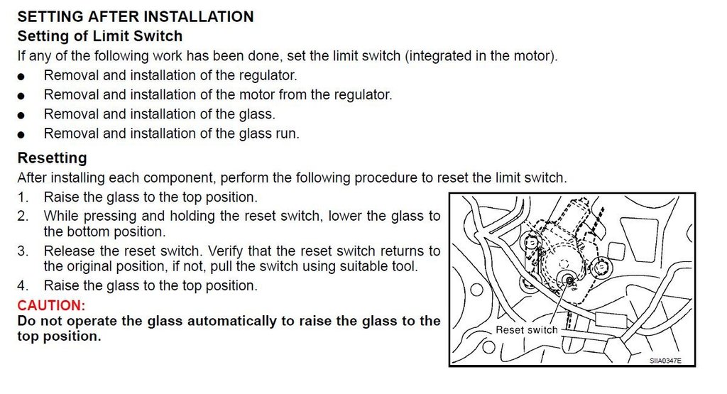
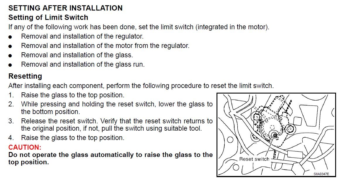
here you go.. (You will need to remove the door panel.then...
-
1
-
-
1 hour ago, MCardoso said:
I will more then happy install whatever parts you need me to install on my truck.
Thank you...but it seems that we just found our man with K9sar.. Discussions are already in process. Thank you for your interest !
-
1
-
-
Welcome !...
For your abs issues, if you do not have obd2 reader that reads them, you can always revert to the manual way... here`s how to retrieve the abs code for your 2001 :
SELF-DIAGNOSIS PROCEDURE
NABR0097S02
1. Drive vehicle over 30 km/h (19 MPH) for at least one minute.
2. Turn ignition switch OFF.
SBR665E
3. Ground terminal 9 of data link connector with a suitable harness.
4. Turn ignition switch ON while grounding terminal 9.
Do not depress brake pedal.
SBR676E
5. After 3.0 seconds, the warning lamp starts flashing to indicate
the malfunction code No. (See NOTE.)
6. Verify the location of the malfunction with the malfunction code
chart. Refer to BR-54. Then make the necessary repairs following
the diagnostic procedures.
7. After the malfunctions are repaired, erase the malfunction
codes stored in the control unit. Refer to BR-42.
8. Rerun the self-diagnostic results mode to verify that the malfunction
codes have been erased.
9. Disconnect the check terminal from the ground. The self-diagnostic
results mode is now complete.
10. Check warning lamp for deactivation after driving vehicle over
30 km/h (19 MPH) for at least one minute.
11. After making certain that warning lamp does not come on, test
the ABS in a safe area to verify that it functions properly.
NOTE:
The indication terminates after 5 minutes.
However, when the ignition switch is turned from OFF to ON, the
indication starts flashing again.(BR-54) below
Code No. (No. of warning lamp flashes) Malfunctioning part Reference Page
12 Self-diagnosis could not detect any malfunctions. —
17 H4 G sensor and circuit BR-65
18 H1 Sensor rotor BR-56
21 H1 Front right sensor (open-circuit) BR-56
22 H1 Front right sensor (short-circuit) BR-56
25 H1 Front left sensor (open-circuit) BR-56
26 H1 Front left sensor (short-circuit) BR-56
31 H1 Rear right sensor (open-circuit) BR-56
32 H1 Rear right sensor (short-circuit) BR-56
35 H1 Rear left sensor (open-circuit) BR-56
36 H1 Rear left sensor (short-circuit) BR-56
41 Actuator front right outlet solenoid valve BR-59
42 Actuator front right inlet solenoid valve BR-59
45 Actuator front left outlet solenoid valve BR-59
46 Actuator front left inlet solenoid valve BR-59
55 Actuator rear outlet solenoid valve BR-59
56 Actuator rear inlet solenoid valve BR-59
57 H2 Power supply (Low voltage) BR-63
61 H3 Actuator motor or motor relay BR-61
63 Solenoid valve relay BR-59
71 Control unit BR-68
ABS works frequently — BR-69
Unexpected pedal action — BR-69
Long stopping distance — BR-71
ABS does not work — BR-71
Pedal vibration and noise — BR-72
Warning lamp does not come on
when ignition switch is turned ON.
Fuse, warning lamp bulb or warning lamp circuit
Control unit
BR-73
Warning lamp stays on when ignition
switch is turned ON.
Control unit power supply circuit
Warning lamp bulb circuit
Control unit or control unit connector
Solenoid valve relay stuck
Power supply for solenoid valve relay coil
BR-75
Vehicle vibrates excessively when ABS is
operating.
ABS control unit to TCM circuit BR-78
H1: If one or more wheels spin on a rough or slippery road for 40 seconds or more, the ABS warning lamp will illuminate. This does
not indicate a malfunction. Only in the case of the short-circuit (Code Nos. 26, 22, 32 and 36), after repair the ABS warning lamp also
illuminates when the ignition switch is turned ON. In this case, drive the vehicle at speeds greater than 30 km/h (19 MPH) for approximately
1 minute as specified in “SELF-DIAGNOSIS PROCEDURE”, BR-41. Check to ensure that the ABS warning lamp goes out while
the vehicle is being driven.
H2: The trouble code “57”, which refers to a low power supply voltage, does not indicate that the ABS control unit is malfunctioning. Do
not replace the ABS control unit with a new one.BR-42 Below
HOW TO ERASE SELF-DIAGNOSTIC RESULTS
(MALFUNCTION CODES)
NABR0097S04
1. Disconnect the check terminal from ground (ABS warning lamp
will stay lit).
2. Within 12.5 seconds, ground the check terminal three times.
Each terminal ground must last more than 1 second. The ABS
warning lamp goes out after the erase operation has been
completed.
3. Perform self-diagnosis again. Refer to BR-41. Only the startcode
should appear, no malfunction codes.-
3
-
1
-
-
Welcome !
-
7 hours ago, RedPath88 said:
Please tell me that SOMEONE has jumped on this AMAZING opportunity?!?!?
And to add to what 01Pathmaker said above, fleurys would not be a member of NPORA's Vendors Group if he was not an exceptional member of this community.
") And he's bilingual to boot!
And he's bilingual to boot! 
unfortunately, no one has....
i'm starting to ask myself if there is any R51 owner that uses them to go off-road or has it just died with the r50 (pathfinder models I'm talking here)... I guess the next step is to go facebook, but I wanted to get someone here who is more implicated in the scene...
-
2
-
Free Lift Kit for your R51 - SFCreation
in 2005-2012 R51 Pathfinders
Posted
Thanks to K9sar, SFCreation is very proud to present you with the R51 lift kit. !!
Made from time proven HDPE polymer they are as easy to install as they can be. The front spacers directly installs on top of the struts and the rear go on top of the coils. Unlike the R50, the R51 does come with adjustable camber; so no extra bolts to buy.
The kit comes with everything including thread locking compound. The front spacers are already assembled with new studs so you don't have to.
Simply the most affordable solution to lift your R51 Pathfinder on the market today.
Of Course, Like the lift kit we made for the R50, the rear spacers are stackable. This mean if you buy 2" of spacers, you can install 1" or the full 2"..
We have the 1.5"fr-1"rr for 1.5" of lift in front with 1" of lift in rear and we have the 2.5" all around.
We offer 2 kits but you can always build your own by choosing the front and rear spacers separately !
Here's a few pictures !
2.5 all around kit
1.5-1 kit
Before lift
After Lift
You can buy the kits and/or the front and rear spacers separately here : https://sfcreation.com/t/pathfinder-r51-platform
Cheers !