
hawairish
-
Posts
2,541 -
Joined
-
Last visited
-
Days Won
270
Content Type
Profiles
Forums
Calendar
Everything posted by hawairish
-
It's funny this thread started as an "engine temp too cold" issue, since now it's actually running too warm.
-
It's kind of funny the temp spread on the gauge. The needle at 50% is what my scanner and NDS says is 220F, but 80% is 230F. Buddy says his truck runs closer to 200F, so I'd expect that to be a more suitable 50% point. Fan clutch is relatively new, bought Dec 2022. When I first got it, it'd roar at startup from being dormant. There were definitely times where it'd be roaring moving from a stop when the engine was getting warmer, and the truck just felt like a tank. So for sure the fan was working then. But, I haven't had that warmed-up roar for a while now that I think about it. The water pump is as good a guess as any. The temp sensor was tested previously and passed perfectly per FSM ranges. The sensor, radiator, and water pump are the only things I've not changed. Since I've got the front of the engine apart for the SAS, now's a great time to change the pump. It's probably the original...I know I haven't changed it in the last 10 years.
-

98 Pathfinder Sunroof Drain Exit Point
hawairish replied to TheCROW163's topic in 96-2004 R50 Pathfinders
Whoops! I'm an idiot. I've still got you covered. Pull the kick panel under the dash, then pull out the foam in there and you'll find the hose tucked back in there. -
There are two sets. The power valves are the ones located on the lower intake plenum ("lower intake manifold collector" per FSM). These were the ones prone to loosening. The actual intake manifold, which the fuel injectors fit into, has swirl valves; these didn't have the loosening problem. With the upper and lower plenums off, you'll see another actuator like the one for the power valves.
-
No need to prop the butterfly valves open. If you’re blowing smoke into any of the small vacuum ports, the smoke will just travel around through the runners on the upper and lower plenums. There’s a lower set of butterflies on the intake manifold, but those are normally open if I recall…and they have reliefs on the butterflies. Beyond that, only thing stopping the smoke from going further are the intake/exhaust valves. As for the misfire counts, I don’t recall being able to see anything cylinder specific, except the ability to shut down each cylinder independently. I’d connect up to double check, but my truck (04) is offline for a while (battery out, engine parts out) and NDS doesn’t allow browsing through menus unless it’s actually comm’ing with the ECU.
-
Exactly right. I can confirm NDSII does not comm with the AT and a few other modules. But, the ECM comm is key; far more data points than over the OBD protocol. I tried using NDSII with my 98 Frontier and it can only do OBD, which is unfortunate. Could've used it the other day troubleshooting some misfires on it. I can get past the smell, but the fact that it lingers for so long is what really nagged me. The little machine I got worked too well at times that I'd have to turn it off and rely on residual smoke to trace the leak. But, no way I'd have found my problem without it.
-
Logic makes sense. Yeah, no EGR on the VQ that I can recall. I had the driver's manifold off to extract busted studs, and there was nothing extraneous about the removal. Unlike my 98 Frontier where the EGR tube nut was so locked into the manifold that I had to make relief cuts in it to remove it! For the last part, the only thing I can think of is just the fuel system condition. When warming up, it's in an open loop and is ignoring all the sensors. When it's met conditions, it'll go closed loop and rely on them. In my case, mine was going to an open loop fault state where it basically wasn't trusting the sensors. BTW, this is where Nissan Data Scan II came in handy for me. I could see each bank's STFT and fuel system state, and correlate it to engine stumbles. What kind of opened my eyes is seeing the banks do them independently, when I just assumed it was the entire engine. Sometimes they were in sync, sometimes they weren't. It also allowed me to see the pattern of occurrence...it was happening every 30s, on the nuts. Have you tried using a stop watch to see if there's some sort of frequency vs. missing erratically?
-
98 Pathfinder Sunroof Drain Exit Point
hawairish replied to TheCROW163's topic in 96-2004 R50 Pathfinders
-
98 Pathfinder Sunroof Drain Exit Point
hawairish replied to TheCROW163's topic in 96-2004 R50 Pathfinders
Go figure...my image host is being wonky so I can't upload a pic or find one I already have that probably shows it. I'll try again later. It's easy to find, though. It comes out under the rear quarter panel, not around the door or wheel well...further back. Look for the bracket that mounts the leading edge of the bumper's side cover to the underside of the quarter panel and it's right behind that. It'll be a tube with a rubber boot/grommet on it, sticking down about 2". If the boot goes AWOL, the hose should still be dangling there. The pic you attached is accurate for the B reference and exists on both sides of the vehicle. If you've got water dripping under the door, I'd think the hose detached at the rearward point A. Might have enough slack in the headliner if you pull the b-pillar trim and door gaskets, but the headliner is somewhat rigid in that space and there's some other insulation items to deal with. -
That's been my understanding, too. Upper sensors control A/F, lower sensors determine upper cat efficiency...at least that's what I believe. System doesn't care about the lower cats (or resonators if Fed-emissions equiped; mine has lower cats). But to that extent, that's why I've always attributed P0420/P0430 to possibly faulty sensors. If the upper and/or lower sensors are buggy, I'd think the delta would be askew. Of course, I could be totally wrong since there are separate codes to assess the sensors themselves. The cat bolts aren't too difficult...it's getting the stupid heat shields off that really sucks, especially on passenger side. A couple 10mm are hidden, tend to be rusted in, and only accessible with small wrenches. After that, just need some sockets and extensions to avoid busting knuckles. I think I only sheared off two or three bolts on the driver's side, lol. In general, exhaust work sucks. In the case of our trucks, you basically need to remove the entire system to pull the cats...at least in my case, there was not enough slack in the hangers to push everything rearward to clear the studs on the components.
-
Time to SAS Hawairish's truck
hawairish replied to hawairish's topic in Solid Axle Swaps, Hardcore Custom Fab
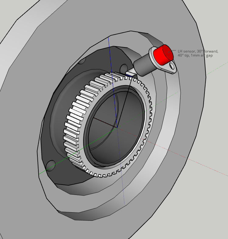
The last few days have largely been spent measuring and CAD'ing things. Latest efforts have been towards designing the plate work on the driver's side chassis rail in the engine bay. In general, I'll plate the top, side, and bottom of the rail about 24" to provide the provisions for the steering box, panhard mount, motor mount perch, and bump stops/limit straps. The passenger side will be different since I only need a plate with provisions for the motor mount perch and bump/limit components. This plate will be bolt on, though. There's vast difference in working space between the LH and RH sides of the rail. I'd have to tear down the engine further (coolant pipes, exhaust manifold) to have better top access, but then there's still an AC line right on top of the rail that I'm not going to relocate or weld around...can't even slip 3/16" plate under it. But, I have a good bolt-on plan. Speaking of motor mounts, I finally welded up a poly set. This will be the gear box placement. Hard to see with shadows, but there's clearance at all points so zero need to cut the wheel well. Placement is 1.25" above the rail, and 0.5" off it. The rail tapers in that area so my plating approach will also square it up. However, this placement will have the metal edge of the radiator right up to it and obstructs the fan shroud. The radiator will be moved 1/2" over and planning to heat the fan shroud up and reshape it. I also forgot to mock this up with the airbox initially, but it cleared just enough. The high pressure line will be routed under the engine. Should work great because it'll be tucked up with other oil lines, is within reach of the pressure sensor, and the pump's OE hardline already points downward in that direction (assuming I can use part of the OE line). Reamed out a tie-rod and the pitman to accept the larger GM TREs. That was sucky process, but it got done. This is one thing where I need to keep in mind that some trail spares need to be modified in advance. Work on the brakes and ABS design still a work in progress. I discovered the R50 calipers mount a lot closer to the hub center than I thought they would...my initial (mis)calculation showed me they'd be fully obstructed, so I had a small panic until I realized I used the wrong measurement in my math. Still, fitment is tight. Going with 4th Gen 4Runner rotors (also FJ Cruiser and 05+ Tacoma) instead. Same nominal thickness as R50 and H3 (28mm), but slightly larger diameter than H3 (300mm vs 315mm vs 319mm). I'll take any additional clearance I can get. Plus, I figure there will be more support for Toy parts in the long run...or in my case, more RockAuto clearance options. But, before I could pull the trigger on returning the H3 rotors and buying the 4R ones, I fired up the CNC router to make a bracket to visualize the general placement. This isn't the exact depth the caliper (it is the exact distance outward it will be), just a general placement so I could confirm things clear. That's right: I can wear sandals in my garage during the winters here. Though, I do wear steel-toed shoes for projects like this. Saw one thread of a guy SAS'ing his Tacoma...he dropped a Dana 60 on his big toe. "¡Adios!" - toenail. I don't know the physics behind caliper placement, but my understanding is it matters. The R50 and D44 calipers are mounted higher, but I have obvious constraints here. The mock-up put them vertically, but I should be able to rotate them up a few more degrees. The main problem with doing these brake mockups is that can't fit the rotors until the hub is turned down to fit inside the rotors (D44 brakes normally mount to the back of the hub). Fortunately, unlike the H3 rotor, I was able to attach the 4R rotor to the backside so I could good reference distances. I'll need to go a slightly different direction for the tone ring. New plan is to make larger tone rings that'll move the sensor up and out, but also avoid taking too much meat off the hub, particularly where it'd overlap where the inner bear race is installed. The general idea:
-
No change, unfortunately. Right now the radiator and hoses are off the trying while I work on the SAS project. I still have the "new" 170F thermostat I originally installed and I may toss it back in, though I don't expect it to make any difference. Per my monitoring on my laptop with Nissan Data Scan, engine temps were nominally 220F and would creep to 230F. This would occur while cruising at freeway speeds even on cold nights...don't laugh since you're in Canada, but cold here this time of year is 40F. They'd also creep while stopped, but then drop a little once I got moving. I think either way, 220F is too hot, but I will note that the gauge needle is just slightly below half way, which has been its normal place for as long as I can remember. So many other thoughts. Maybe the fan clutch isn't pulling like it should (it's pretty easy to stop when the engine is >220F). With the radiator off I may try to flush it or replace it. Maybe the water pump isn't circulating. The R50 VQs have an upper thermostat for 203F bypass that I may even just remove, since it didn't exist on other VQs, including the JDM R50. Anything to ensure that coolant is actually pumping. Given the procedure I did for bleeding, I had rather high confidence that I got air out, since the tube approach I did offered visible proof...but I was pretty pissed to see it doing this all over again.
-
The things I'd do to get 15.5 mpg on my truck... ... It's a little curious that both cats are throwing codes, but as Slart mentioned they could've eventually been damaged. I know on mine I had the cats off back in 2022 to confirm they weren't clogged, but no real means to test for efficiency of course. Still, but codes is odd...even with my woes, I only ever got the bank 2 code. From what I understood when doing my investigating, if the STFT is staying under +/-10% and can closely meter around 0% at idle or cruising, then that seems healthy. When I was diagnosing mine, my truck would just creep from 0 to 25 over 30s intervals and then just "reset" back to 0%, which is when the engine would stumble. What I had realized is that each bank would do that on separate intervals...the hard stumbles were when both banks were in sync. But, it became clear that each bank could meter fuel independently, which was a new concept for me (engines aren't my thing). Before dropping coin on cats, I'd do a leak test. How are the O2 sensors?
-
Not sure my recent woes align with this, but I had multiple air leaks at the o-rings on my fuel injectors due to them being slightly undersized (seemingly my mistake). The excess air would eventually cause the engine to stumble every 30s, regardless of gear selection. RPMs would drop to 600 and engine would run rough. I've also been throwing a P0430, but it's been deemed unrelated to my issues. I threw P0507 and P0171 codes previously, which are what suggested a leak. Dropped $80 on a smoke machine from Amazon and it exploited the issue. The economy is in crisis when baby oil is $10. I also initially thought my issues were alternator related. The original one crapped out back in June and I slapped a cheap replacement in. I had never noticed an issue before the new alternator (I had serviced the injectors a year before), but I have one of those voltmeter pods and it indicated things were healthy (around 14.3V engine running). It sometimes see the voltage drop when the engine stumbled, so had concerns of what was causing what...was bad alternator causing the engine to stumble, or was the engine stumbling causing the voltage to drop? In the end, alternator was not the problem. Other things I had done: Cleaned/moved around plugs, coil packs. Swapped/cleaned MAF (they have aerosol cleaners at parts stores) Checked compression Idle relearn Throttle position relearn PCV check Throttle body clean Obviously none of the above solved anything, but looks like you've done most of those. May be time to check for leaks.
-
Usually the only reason to replace the valve covers are if the spark plug seals are leaking. They are not are not intended to be serviced, and as such they are not replaceable unless you want to do surgery on them. They were replaceable on the aluminum covers. Other notable is that the #1 ignition coil on the aluminum covers is different from the other five, and none of them are the same as the 02+ trucks with the plastic covers. On the plastic covers, all the coils are the same. I can confirm you can use an older style coil on a plastic covers, but it there's a small gap between the coil and the cover where the mounting screw goes. Stands to reason that if you tried using your coils on the aluminum cover, you'd have to turn them a little to ensure they were fully seated, and wouldn't be able to use the mounting screws. Long story short: keep the plastic covers and just change the valve cover gaskets. Don't forget to seal the front corners as prescribed in the FSM.
-
Time to SAS Hawairish's truck
hawairish replied to hawairish's topic in Solid Axle Swaps, Hardcore Custom Fab
Slow progress yesterday and today. CAD'd up the poly motor mounts and am going to try to get the pieces cut tomorrow. Made a bit of a drive today to pick up some FJ80 radius arms. Had been eyeballing a crusty set on eBay, but with tax and shipping they'd be about $250. Fortunately, the guy's not far from here so I got in touch with him offline...done deal at $80. They were as crusty as expected, so they needed some wire wheel'n. And now I have RAs, into them about $140 after gas and new bushings. And here's what we're shooting for... This orientation is how the FJ80/FZJ80 is set up. In that world, some guys will flip the RAs to be atop the axle, and I was hoping to do the same but the rear subframe mount would ultimately limit up-travel unless I put a lot more lift back in. But, this setup works fine for me. I need to drag the axle back out to cut and grind the leaf spring perches to tuck the arms up. Passenger side shouldn't be too bad, but the driver's side is integrated into the cast so it's just a big chunk of steel I'll need to get through. I'm going to see if I can move the arms outboard so that I'm just dealing with tube, but I think the tires will just scrub on them. As far as rear mounting goes, that bushing is almost directly under the transmission crossmember, which is perfect. Plan there is to build a new crossmember that has the mounting provisions, and also clears the driveshaft. I plan to reinforce the mounting area and add more attachment points. -
Time to SAS Hawairish's truck
hawairish replied to hawairish's topic in Solid Axle Swaps, Hardcore Custom Fab
Not sure if this counts as point of no return yet, but the truck has officially been modified. The pivot box brackets are gone. Spot weld drill bit did the trick for the most part; fought keeping it centered sometimes. Radiator had to be removed to gain access, of course. I did a brief mockup of the steering box and I was initially hoping to not have to cut the wheel well for clearance, but it might be inevitable. It'll be tight in that space. Hopefully it doesn't require me to move the axle back further, am liking where it sits now. Tubing got cut today for the GM TREs and the bungs tacked in. I'll cover steering links at a little date when I have more mocked up. -
Time to SAS Hawairish's truck
hawairish replied to hawairish's topic in Solid Axle Swaps, Hardcore Custom Fab
Initially, I looked into threaded fittings and I think I identified all the ones I would need, so the hope is that a crimper isn't even necessary. Main concern is just the high pressure side as I will retain the pressure sensor on the line. Main parts are just the banjo at the pump, a tee for the sensor, and fitting at the gear box. Low side is just hoses through a new cooler and hose clamps. ... Slow progress yesterday, mainly just a full mock-up day. Right now, axle's looking real good 2" forward. I originally had the truck lifted about 5" higher than it was previously, but lowered it down to about 3" higher. Supposing I can get it at that height, that'd net about 8" of lift from OE height which I guess feels low for a SAS project, but in reality meets my project goals better. The rear is currently about 6" over stock and at this 8"/6" stance, the truck is perfectly level according to my sliders. When the front is done, I will be redoing the rear suspension to also move the axle back about 2" to center it up in the wheel well and at that point I'll probably lift another 1-2" to get some rake back. -
Time to SAS Hawairish's truck
hawairish replied to hawairish's topic in Solid Axle Swaps, Hardcore Custom Fab
Phase 1 (Disassembly) complete! Finished removing all the power steering components, basically leaving only the steering linkage at the firewall. Little leaks and dirt saturation all over the pump and reservoir, both of which will get cleaned up, rebuilt, and new hoses. Leaning towards buying a hose crimper just to do the high pressure line myself when the time comes. First fabrication of the project was making engine slingers. Once I pulled the p/s pump I could see where the holes are for factory slingers, but it basically mandated use of those specific genuine tools and it's a pretty lousy spot. Instead, I made a bracket to mount where the p/s pump was, and another that attaches to the motor mount bracket. With engine supported, I could drop the subframe and spacers...clean slate! One thing's to be said about preparing the space on a unibody vs. a framed truck...there was zero grinding or cutting involved. Everything just unbolts and that's it. I'm going to try to keep other things as bolt-on as possible. For sure, the area where the steering gear box will go will be plated and sleeved, so welding required there. Phase 2 (Mock-up) began by dropping some plumbs and getting the axle in place. For now, I just needed to get a solid feel about how much space I'll have between the tires and the wheel well skirts. Looks like it's almost 7", but that might be a generous number. Coil springs I'm eyeballing (likely a Jeep WJ or JK spring) appear to be about 5" OD. I'll get a little more space if I run the 1" spacers I already run, and I prefer that stance overall. Initial observations are good overall! For now, I'm using the Heim steering setup for mock-up since it's already the correct length, but it'll get chopped up a little to use the GM TREs. The JK adjustable track bar looks like it might be a really good match length-wise for the drag link, but numbers still pretty rough until I can mock up the gear box. Plenty of oil pan clearance, though I still want to move the axle forward another inch or two than shown in pics. Good clearances so far. As for the radius arms, I've been looking into either making custom arms or using a OE set from an FJ80. I'd prefer to minimize work if I can since pretty much everything else has to be fabricated from scratch. There's a set somewhat local to me that needs some cleaning and new bushings; easy enough. Length looks to be about perfect, too. The tails should end up around where the transmission crossmember is, which will work out great building up a new crossmember for the mounts and driveshaft clearance. Next step is to start mirroring the subframe mounting points so I have an idea of how to reattach the motor to the chassis and space for mounting provisions. Also need to pull the motor mounts, get them jigged up to make poly versions, and clean up the chassis rail where the gear box will go. -
Time to SAS Hawairish's truck
hawairish replied to hawairish's topic in Solid Axle Swaps, Hardcore Custom Fab
All good. Yeah, our VQ is just too complicated and so poorly supported to justify changing things, unlike every other VQ35DE that's actually supported well. I've given far more thought to turboing the KA in my Frontier, but recently I've been looking into EV swapping it instead. I really wish I could find those videos again. Truly amazing work. Lost in the ether. 12 mpg is very rough. Was 10 for a while, which made it just miserable to want to drive it anywhere. I'm sure it's because my tire/gearing setup right now is nearly 8% under-geared, so dropping to 3.5% over-geared will lighten loads up considerably until it's time for new tires. And thanks for the support! I'll take all I can get! -
Time to SAS Hawairish's truck
hawairish replied to hawairish's topic in Solid Axle Swaps, Hardcore Custom Fab
Well, project officially began today. Had some helping hands: Just need to figure out how to sling the engine up. No good attachment points on the passenger side at all. Once I figure that out, I can pull the subframe and finally have a clean slate for mock-up. -
Time to SAS Hawairish's truck
hawairish replied to hawairish's topic in Solid Axle Swaps, Hardcore Custom Fab
Ha, hopefully not too crazy, but surely not the craziest. There were videos of this one R50 that surfaced the other year of probably the most amazing Pathfinder out there. SAS'd, dual axle steering, and an amazing suspension setup I can't even describe. The work was pro. Dude even had a pet duck. F'n hero. Wish I still had the links. Define power train upgrades, though. I do have dual lockers and crawler gears, and it's been an amazing setup so far. Engine performance wise...there's not really anything available and mine has been such a hog the last 2 years that I don't think I want anything from it beyond stock performance and better fuel economy (I'm barely at 12 mpg after fixing a major intake air leak that went undetected for a while). I have a few side quests that hopefully I can address when there's down time, including changing (or attempting to change, 2nd try) at least the upper cats. "SAS" and "fuel economy" probably shouldn't be bundled together, but I think the new gearing's going to help a bit. -
Time to SAS Hawairish's truck
hawairish replied to hawairish's topic in Solid Axle Swaps, Hardcore Custom Fab
Looks like I've talked myself into doing a radius arms setup at the 11th hour. I'll just have to keep things on the cheap affordable side as best as possible. Conveniently/suspiciously, my Facebook feed today showed a local Marketplace listing for an adjustable track bar (panhard bar) and OE sway bar with disconnects from a JK Wrangler. Met up with the guy, talked shop, observed the cringe-face when I mentioned "unibody", and made the deal for $100 for everything. Track bar could be a $115 Amazon knock-off, a $150 Rough Country unit, or $325 Teraflex unit because they are identical. Key thing is that it's shaped to wrap around the diff cover and it's adjustable...and within the range I'd need it. Does need to be freshened up and bushings replaced, but that's easy stuff. The JK sway bar is straight and beefier compared the R50 unit, which I was already planning to reuse but poses some complications because of the shape. I'll probably toss or sell the disconnects that it came with; they're worn, but appear to be a rather expensive Teraflex set. I plan to run disconnects either way. Engine support bar arrived the other day and the garage is as clean as it's getting. I may start tearing things down in the morning. To be honest, this project terrifies me more than any other I've done so I'm dragging my feet to dive in. Pulling stuff off is easy, but there will eventually be a point-of-no-return moment that I hope I don't dread. -
Damn. That’s terrible, man. Great looking truck! Sorry to see it this way. Keep us posted how it works out, please.
-
Time to SAS Hawairish's truck
hawairish replied to hawairish's topic in Solid Axle Swaps, Hardcore Custom Fab
Ah yes, let me expand on that. This part of the project is one of the main reasons I became more willing to move forward on it. In short, I'll be using the R50 tone ring. I had a junk R50 spindle and hub laying around. Ring pops off with a little effort, and the ID is just barely large enough. The backside of the D44 hub will get machined down to about 1/8" thickness (about the thickness of the flat lip at the top). Since the H3 approach was already laid out at the time, I did look into using the GM ring initially. But it's 55-tooth vs. the R50's 48-tooth. Any mismatch would/should screw with the ABS and ECU. Tried to find suitable matching rings that could maybe be machined down to fit the rear axle shafts, but that sort of search proved difficult. One more notable about the brakes: whenever I've read about Nissan guys using the D44 brakes, they always need to jump to a larger brake booster and/or master cylinder. The D44 calipers are monster one-pots. I was stoked to see that the H3 rotors were the exact same thickness as the R50 rotors, and very similar diameters. Using the R50 calipers means not having to change anything about the system, which is huge. The next hope is that both the ABS and brake hose are long enough to support axle droop with my setup. It looks very promising considering that the lines snake around the strut and have a lot of slack. Thanks for the offer about the WD21 shaft dimensions. The FSMs have so far provided the base dimensions, except the slip distance. I was also really surprised to see in the FSM (and echoed by Nissan Nut) that the WD21 driveshaft also uses the oddball u-joints the R50 does. All the other trucks had the 1310 joints (same true for the rear shafts). What gives, Nissan?