Leaderboard


Popular Content
Showing content with the highest reputation since 03/16/2024 in all areas
-
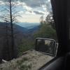
Thanks all, turned out to be a simple fix- the hose had just pulled off the barb on the drivers side of the radiator. I reseated it and move the spring clip to where the hose wasn't indented from it. Thanks also for the tip on fill-run-fill-run. It took quite a few times of letting the fluid work through before the dipstick continued to read full. I think that when I backed up in the deep snow, the plastic under guard scooped up a bunch of snow and ice and pushed the hose sideways until it popped off. A good thing to keep in mind for the future- it would have been worth it to dig the snow out.3 points
-
Just following back up after I found the issue... It was a bad wire between the dual pressure switch and the A/C switch. By walking through the service manual diagnosis steps for a compressor clutch not engaging, I narrowed it down so that I knew there was something fishy between the dual pressure switch and the A/C switch. From there I ended up getting a cheap short detector from amazon and ran it along the wire harness that runs between dual pressure back to the dash A/C switch, and found the spot where the signal drops. Turns out the harness was damaged there. I must've accidentally cut it on some previous work. Here's the short detector... it worked pretty good for the price: https://www.amazon.com/dp/B07BC4X28Y?psc=1&ref=ppx_yo2ov_dt_b_product_details My advice for DIY A/C diagnosis is to follow the service manual steps. They were systematic and worked pretty well for me in diagnosing the electrical problem.2 points
-
I just want to put out a general Thank You to the new members signing up and/or posting an introduction. We are almost up to 1700 4300 9500 11,600 members (although most are not active) and have new members signing up almost every day with newbie's posting intro's in this section several times a week. Don't be shy !! We have a good community here and like to hear from newcomers. New people and new ideas are what keeps things alive! With input from all around the globe, we get to hear about issues, options and mods that may not be posted if this were just a regional site. Keep in mind though that with world wide members, humor and comments can sometimes be misconstrued, so have patience and be considerate to one another. One of the things that keeps this site so pleasant and friendly is that it is a family oriented site with everyone welcome. Please try to be PC and refrain from overt vulgarities, we are all friends here. Welcome and enjoy !!! Bernard1 point
-
I did everything from the bottom (3.5L). In fact, only way I could really even get up there was with the lower cats off (or resonators on some models). Getting the head shields off the uppers was the tough part…a few 10mm are in very tight spots. Some sheared off due to rust. Penetrant wouldn’t hurt. Once the shields are off, you’ll still need/want socket extensions and wobbles to give yourself leverage below the chassis…working space is still tight. Access to the RH upper O2 sucks. All others are easy (LH upper from the top). I can’t remember if everything was nuts, but I want to say some were bolts. I know I sheared a couple on the drivers side and had to pull the exhaust manifold off to repair. Passenger side is a nightmare…fortunately didn’t have to remove that manifold and didn’t shear any. Also, I basically needed to remove the entire exhaust system to pull the uppers off. There wasn’t enough slack in the hangers to pry things backwards, so I removed everything starting from the rear.1 point
-
@EricCR Forget OEM. 10x https://belmetric.com/m14x1-5-fine-din-6921-flange-bolt-class-10-9-wrench-18mm/?sku=BFD14X1.5X80YLW @ $3.54/ea 10x https://belmetric.com/din-6927-fine-full-wrench-class-10-top-lock-flange-nut/ @ $1.54/ea Class 10/10.9 hardware, yellow zinc, OEM size and function (prevailing torque lock nut). Only real downside is they are not JIS spec, so they need different size wrenches than you'd normally use on the truck (18mm and 21mm). Buy 10 sets because there's a price break that's less than a buck more (8 @ $49.92 vs 10 @ $50.80 before tax/shipping). Haven't used Belmetric before, but will be soon.1 point
-
Hey Eric, I appreciate the reply. Yes, agreed. I didn't mention that specifically, but that was definitely part of it. The service manual had me check continuity on various parts of the circuit as well as voltage being supplied when the ignition was on. Basically the compressor runs on 2 circuits, bound by a relay. You have a circuit that has the dual-pressure sensor -> A/C switch -> Fan switch -> ground, and you have a circuit that runs to the compressor -> ground that is only complete when the first circuit completes. The service manual has you systematically check that 1) each circuit has voltage, and 2) that there's continuity between each link. It was only when I found that there was no continuity between the dual pressure sensor and the A/C switch, is when I broke out the short detector and ran it along the wire to find the breakage. It was a good learning experience since I had never dove into electrical issue diagnosis. I know its mentioned a bunch in this forum that has been so helpful to search, but NICO club has the service manuals for pathys. https://www.nicoclub.com/nissan-service-manuals Between that in searching here I've been able to DIY pretty much everything since I bought my R50.1 point
-
Hopefully it's just the motor. Remove the plastic cover inside of the rear hatch, unplug the motor, and see if the wiper switch still pops the fuse. If it doesn't, then it's probably the motor, though I would test the motor before replacing it on the off chance unplugging it just broke the circuit to some other faulty component. If the fuse pops without the motor, or the motor tests good, you'll have to do some digging. EL-69 of the '90 manual (free download from cardiagn.com) shows the whole circuit. EL-90 has component locations, EL-93 and up should help you find the relevant connectors. By disconnecting those, you can narrow down where the problem is. If the fuse doesn't pop anymore with 13B disconnected, then you know the problem is in the hatch. If it still pops with 297M disconnected, you know the problem is between 297M and the dashboard. You could unplug the amp and/or relay. IIRC they're behind the lower trim, left of the rear cargo area. If unplugging one saves the fuse, either that component or something downstream is bad. This approach should narrow stuff down so you're not screwing around chasing wires at the wrong end of the truck. If you can't be arsed to do all that, or your troubleshooting leads you to the rear hatch harness, check the wiring between the body and the hatch. That's the only place in the circuit where wires have to flex, so that's where I would expect the wiring to fall apart first.1 point
-
Thanks for taking the time to update us on the solution. It may help someone at some point. If you have a multimeter you can also find open circuits by measuring resistance and/or continuity, just in case you already have one.1 point
-
Maybe. Ignition switch failures tend to cause all sorts of weird glitches and it's common in Nissans for it to fail, so I'd change it, it's a simple job and relatively cheap. But I would also look at the relays in the engine bay. Try swapping identical relays and see if some of those issues go away. To give you an example: my AC was randomly spewing warm air. I replaced the HVAC module and it was doing the same thing. I even disconnected the air mixing actuator. In the end the problem was the relay that controls the AC compressor which was intermittently failing and I found it by swapping it with the fog light relay. My fog lights started acting up and the AC started working fine. So check relays too. Start from the cheaper, simpler things then move on to the complex. I'd leave the starter for last. It's not easy to replace, access down there is terrible.1 point
-
1 point
-
Get 8 of 54368-0W02A. You can cut the tips if they are too long. @hawairish and I did this for mine.1 point
-
Have you ever gotten around to selling the CAD files or any more complete kits? I’m definitely interested in the front brackets, or any updated versions you may have1 point
-
Yep, one bolt per side.1 point
-
Its supposed to only be one bolt per. a pack of 2 is all you need https://www.amazon.ca/gp/product/B000CB2GOU/ref=ppx_yo_dt_b_asin_title_o01_s00?ie=UTF8&psc=11 point
-
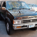
Echoing the above replies. That "4WD" light is specifically a warning lamp for the system, not an indicator that you are in 4wd. If it stays lit, it means a malfunction is detected. Generally, the system prevents Auto/4H/4L engagement when malfunctions are present, so if you've not personally engaged 4H and 4L to feel the difference in crawl speed, I wouldn't trust the dealer's assessment at all. In essence, there's a diagnostic pattern that can be perform on the truck using the ignition switch, the dial switch, and the transmission shifter to enter a diagnostic mode where the 4wd lamp will blink a pattern that corresponds to one or more fault codes. I highly doubt the dealer will allow you to perform that process, use a diagnostic scanner (a generic OBD scanner will not be able to pull these codes), or otherwise take it to a mechanic or dealership for inspection (at your expense). Truck otherwise looks to be in reasonable shape for age and mileage, but I'd strongly advise walking away if you're unable to pull the code(s), unless the vehicle is potentially acceptable for use in 2WD/RWD. The reason is because this "All Mode" transfer cases uses input from nearly all other modules (ECU, transmission, ABS, for example) in order to operate multiple motors, pumps, and sensors. There are also dozens of potential fault codes, not to mention that multiple fault codes can be present, and not necessarily isolated to the transfer case system itself. Without knowing what codes exist, it's impossible to know the real cost of repair, but it can become substantial quickly (old parts, Nissan-only parts, electronic/electrical parts, difficult to access/remove parts, etc.). If you're set on the platform and want 4wd, you can find Pathfinders with a part-time transfer cases that have a mechanical shift lever; they lack the Auto (AWD) function, but they also lack all the complexity and are significantly simpler and more reliable. Some SEs, all LEs (?), and all Infiniti QX4 with 4wd had the All Mode system.1 point
-
The newer Moogs will fit all the same, but the bracket/tab used to secure the ABS wire is different. The older trucks used a J-shaped hook that bolted to the arm. The newer style has a forked tab that a rubber boot on the line presses onto. If you take a close look at the pics on RockAuto, you'll see the difference. Nothing some cable ties can't resolve, though. The parking brake cables attach the same on both styles, noting that driver's side uses two tabs to attach the cable, but the passenger side only uses one bracket, but most RH options show both tabs.1 point
-
I'm hanging in the same situation I just sold my stock Xterra and bought a 2012 Pathy. I fund a youtube video from a chech guy, he took an 8.5 min music video pack'd with lot of info what you nee for 2 different lifts! Just look it up, it's pretty straight forward.1 point
-
Hey R50 people! You might have seen my posts on Facebook groups or instagram, but I also wanted to be present here as I've enjoyed browsing this forum numbers of time. Those of you who don't know me, I'm based in Vancouver BC Canada and I created a sweet roof rack for all R50 models. I was inspired by Prinsu obviously and since there are no aftermarket solutions for R50 I decided to make my own rack. Please check out some details, information, manual and more photos at my google drive: https://drive.google.com/drive/folders/14yxt2aZX2_KDKsw74M9Ft5XpMms7hF-H?usp=sharing Let me know if you have any questions! I've sold a few already so you might start seeing those racks on R50s! Thanks! Pawel
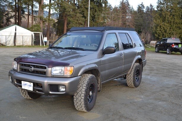 1 point
 -
Glad you got it sorted. Aluminum to steel usually has these results after 30 years haha.1 point
-
SUCCESS, ladies and gents! Long story short, I think hammering on the m/c is what did it... The extended version, I used a conical grinding bit on the rotary tool, to dig enough of a groove to get some blows in with the chisel. (Never got close enough to the threads to make a "seam" there). Was getting frustrated at it still not coming loose, turned my attention back to hammering on the m/c from the inside, peeked my head back around and saw that there was more clearance now at the top stud! Then gave it a yank, and voila! Thanks again for all your help and suggested approaches!1 point
-
I'm not aware of any size differences, and I'm surprised to not see the parts weren't superseding, but they should fit all the same. The difference is probably the vibration dampeners that are attached to the bar. Only real changes across the entire 96-04 range relating to rear suspension were in regards to shock mounting, and even then 96-99 were the same style.1 point
-
Hey there yall, im freshly signed up now, but ive frequently used this forum over the past few years this is my 1997 r50 lifted 2 with 33x12.5 tires stuffed underneath her lol, used to be local to washington but now am located by little rock arkansas cant figure out how to adjust my photos properly from one drive yet, other wise i would add a photo thanks for the add here1 point
-
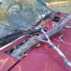
I finally said screw it, let's fix the rust issue. I've got rock sliders in a box, replacement body panels, and a tire carrier sitting around, but I couldn't see myself attaching these all just mere inches from the crusty metal cancer that's been slowly growing over the last 5 years I've owned it. Upon starting the project I had rust holes in the rocker panels that I wish to protect with rock sliders. Lots of crumbly rust around the rear fender flares and a small rust hole in the uniframe in the rear driver wheel well. There was some surface rust and some flakey bits underneath by the spare tire carrier. So I ordered some slip on quarter panels and rocker panels from Nor/Am body parts. First things first, let's attack structural rust so I began by removing the gas tank, fuel filler assembly, evap system, hitch, spare tire carrier assembly, bumper and part of the upper control arm mounting bracket. Next I began opening the hole in the uniframe. Working my way forward... which is downhill, things got better and cleaner so I stopped. Working my way rearward, things stayed crusty. I ended up opening a large section of the uniframe to look inside. It was rusted internally all the way back. That didn't seem to make much sense because you'd figure that the rust problem would be worse in the lower portion of the frame toward the front. Also the exterior of this uniframe rail was in much better shape than inside. Examining the frame rail, I saw the evap system vents into the frame rail. I know for sure that something has always been funky with the evap system because I could smell fresh gas from time to time from the rear of the vehicle despite never having anything be wet or have codes on the dash. I'm assuming the part called a water separator was fouled causing moisture vapor to vent into the frame rail. Ok, so this is gonna be an ordeal to fix. I decide to hit the brakes on that rail and moved to a cross beam that the tire carrier mounts to. I began cutting out the rust to find a fair amount of rust inside this. I stopped cutting when the crusty rust transitioned to mere surface rust. Next the panhard mount on the chassis had some flakey rust so the 'ol hammer test confirms that it's also toast. After releasing the panhard bar I began cutting the lower portion to see how bad it is inside. I lucked out and found that just the lower portion was crusty. This mounting protrustion is connected to a structural cross beam in which, as you guessed, had some crusties. After cutting this open, I find rust at more or less the far ends of this beam where it joins the main frame rails . I'd rather not lop off the entire panhard mounting point, I so I began removing brake lines and fuel lines to clear a path to where I can cut an access hole at the upper most portion of the mounting point. That's more or less where we ended up this week. It's definitely not an exciting project to write about and there's a million other things I'd rather do right now but I figured I'd sort of roll out some updates on this until we get to the finish line. Every time I regretfully walk into the garage, I gotta remind myself my ultimate plan for the vehicle is to keep it forever and keep it in better shape than I originally bought it. The blessings I have working for me right now is the valve covers have always leaked and oil kept most of the rust away from the front as far as I know. Mid section seems ok too. So what's next? More rust cutting, more bracket removing, and possibly divorcing the axle from the body. The axle has a solid amount of rust scale everywhere that would eventually eat the suspension mounting points so that's gonna need some love too. I plant to get to a point where every structural beam is opened up and all crusty sections are cut out with a die grinder or sawzall. After that, everything is getting either the grinder, flap wheel, bore polisher or sandblasted to bare metal. Inevitably there will be trace amounts of rust that would be addressed with phosphoric acid. Apparently this converts Iron Oxide to Iron Phosphate which halts rust progression and becomes a paintable surface. Next step replacement sections of steel will be welded back in. Any female threads that had bolts snap off will be drilled out and re-tapped. Any male studs that broke off in a nut, will be welded back in. After welding and sanding, I'll figure out what rust inhibiting primer to use and apply that. I plan to apply this internally in the rails with a special spray I have. Most likely would finish off the axle and underside with bed liner of some sort. After that, new plastic clips, new extended brake hoses from Taylor, and rubber hoses. Then we can resume with quarter panels, rocker panels and learning how to paint a vehicle. Until next time, peace!1 point
-
As Chris mentioned, it could be the trans cooler hard lines or It could also be the rubber portion of the line which is the best case scenario... Just go to the auto parts store and ask for transmission line hose of the same diameter and you're good to go. It could also be the radiator. The radiator has aluminum barbs for the trans cooler lines that can snap. I've snapped mine off on the trail before. Once you find the point of exit for the fluid and fix it, a simple refill should get you mobile again. I'm guessing 4 quarts should get the thing rolling. May need a 5th quart to get where you need to be on the dipstick. Driver side cooler line is hot fluid exiting the trans. Passenger side is cooler fluid returning to the trans.1 point
-
Nice when it's the simple fix! Good thinking using the fader to work out which output was which.1 point
-
That's so awesome, basic trouble shooting for the win. I always say when in doubt look again. Glad you you were able to figure this out and now you can enjoy having music in your R50 once again. Chris.1 point
-
I agree that $50 is too much, but you won't find anything to match OE easily. Believe me, I've looked. The OE bolts are flanged M14 x 1.5 x 80mm (not including those nubs at the end), and the nuts are PTLN flanges. You won't find flange bolts like that, unless you want to pay >$20/ea for some titanium ones. You can look for M14 x 2.0 and 9/16"-18 x 3.25" sizes, but you won't find them in comparable quality to OEM. Either the flange won't be available (not even sure it exists for 9/16"-18), it won't be zinc plated (plain or black-oxidized hardly offer much corrosion resistance), or the length (especially 3.25") will be tough to find. You can find hex bolt options no problem, if you're willing to change to flat washers. But look, forget all that. The FSM doesn't spec replacing the bolts...it only specs replacing the nuts. If anything, buy a couple or more of the short bolts (54368-0W02A) depending on how gnarly yours look and 8 of the PTLN nuts (08918-6441A). That way you follow spec, and have some bolts handy should you have to destroy them out (it happens when you round a nut) or the threads get boogered. Short bolts are $2/ea and nuts $1/ea from nissanpartsdeal.com or courtesyparts.com (these are actual Nissan dealerships; use "nis10" at Courtesy for a discount). The long bolts (55080-0W00B) are what drive the cost up, at $6/ea, and they have those stupid shear-offs that prevent fitment in some places...avoid them.1 point
-
Here's a quick how-to for replacing the CV axle: TOOLS NEEDED: 1. Jack 2. Jack stand(s) 3. Lug wrench 4. Snap-ring pliers (about $10) 5. 3/8" ratchet/driver 6. 12mm socket or ratcheting box wrench 7. 17mm deep socket 8. Screwdriver or putty knife 9. Vise-grips or large pliers 10. Hammer REMOVAL 1. Jack up truck and place on jackstands under the chassis (not the A-arms). 2. Remove tire 3. Remove hub cap on drive flange. Use a flat screwdriver or putty knife to pry it off as you rotate the hub cap with vise-grips. 4. Using snap-ring pliers, remove the snap ring on the CV axle splines (behind the hub cap you just removed). 5. Using a 12mm ratcheting wrench or socket/driver, remove all 6 bolts holding the inner CV axle to the differential flange. To access each pair of bolts, rotate the brake rotor and then to keep it from rotating while loosening the bolts, stick a screwdriver through the brake caliper and the brake rotor vents. 6. Remove 3 17mm nuts from the ball joint and pry/wiggle the ball joint studs out of the A-arm, then swing the A-arm downward 7. Tap the outer end of the CV axle with a hammer to dislodge it from the drive flange and slide it towards the center of the vehicle through the opening created by swinging the A-arm downwards. 8. If the thrust washer is still attached to the outer shaft of the original CV axle, remove it and install it in the same orientation on the new CV axle. INSTALLATION 1. Slide the CV axle back into the hub through the opening created by the swung-down lower A-arm. 2. Hand-thread the 6 12mm bolts holding the inner CV axle flange to the differential flange. 3. Reinstall ball joint and tighten the 3 17mm nuts 4. Tighten 6 12mm bolts holding CV axle to differential flange, first, one per each pair of three, then tighten the second one of each pair. Don't forget to insert that screwdriver through the rotor vents to keep it from spinning. 5. Reinstall snap ring. You may need to pull axle fully through the hub to fully access to the snap ring channel. 6. Reinstall hub cap. 7. Reinstall tire 8. Remove vehicle from jackstands DONE! NOTE: Alternatively, in lieu of removing the ball joint to provide clearance to pull out the CV axle, you may opt to remove the large bolts holding the A-arm to the subframe. There's one long bolt and nut at the front and two bolts at the rear of the A-arm. I think they're 7/8 or 21mm. I forget. This can be more inconvenient because you'll need to remove the splash guard to do this, and those bigger fasteners might need a 1/2" drive or air wrench to remove. The benefit is that that you don't have to fight the torsional resistance of the A-arm bushings or wrangle the ball joint studs through the A-arm, which can be challenging due to the weight/angle of the strut/knuckle assembly.1 point
-
Aspects of a subframe drop include: -The subframe drop is 4 blocks. You can design it several ways, but honestly its simple. You are just making a rectangular spacer between the bolts and pushing the whole subframe down. Mine are 4" height. -The engine requires 2 blocks the same height as the subframe drop blocks. These are also very simple design. Again just a spacer between bolts, rectangular with no angle. -You also need to lift at the front suspension. However there are no longer struts available, so anything longer than AC coils will lead to severe topping out. So you will need spacers here too. These are NOT straight to keep the geometry right. If you are designing your own lift then you'll need some trial and error to make the angle right. My spacers are 2.5" and the rest of the lift comes from the AC coils. Most people have used 4" spacers plus AC or OME coils to achieve 5-6" total lift. -You need to extend the steering shaft. I think most of us are using a honda U-joint with a spined shaft that matches the R50 shaft for the extension. I do not know if a straight extension would work, but I can confirm that this method does. -The rear lift is much simpler than the front. You can use straight cylindrical blocks, longer coils, or both in combination to achieve the desired lift. I have 3" blocks and AC coils. There may be coils from another vehicle that fit, or you can order custom coils. -You will want longer travel shocks in the rear -You will need new bump stops in the rear and possibly limiting straps -The stock panhard rod will be out of stock specs and force your rear axle towards the driver's side. The setup will work like this, but ideally you should make a drop bracket or a longer rod. Adjustable upper and lower control arms can be considered as well. -You'll need longer brake lines front and rear -You'll want to extend both differential breather tubes -Your rear swaybar will be out of whack. I modified a stillen swaybar with longer links that can be disconnected with a single bolt. The front will still work if you want to keep it. -The front skidplate will no longer work, you'll want a new one. -Ideally you should add lateral bracing of the blocks up front. The SFD is kind of like putting your vehicle on stilts, and actions like laterally winching could twist your subframe. A solid skidplate will help. -You'll need to adjust the routing of your front ABS line to prevent stretch -If you are going with larger than 33" tires you will need to do a lot of trimming even after this lift. Of course you'll want to re-gear as well, especially if you have 4.3's. The front blocks: The rear blocks: The engine spacer: The steering extension: The skid and driver's side front block: Installed: I owe Tyler Morgan thanks for doing all the research and providing me with a Prado prototype. You will run into hiccups with any custom project like this. Installation is a lot more involved than doing a regular suspension swap and you will need multiple jacks and stands. Air tools and an engine hoist would make it easier. However, I had very little experience and did the installation alone with only hand tools.


 1 point
 -
hi archer. got bow? http://www.nissanpathfinders.net/forum/index.php?showtopic=69571 point
.thumb.jpg.3b55d9a307419d052e117782307fc17d.jpg)