Leaderboard

Popular Content
Showing content with the highest reputation on 02/02/2021 in all areas
-
Hey gang, Over the last 18 months I've really come to love my WD21 Pathfinder! So many quirks and features. If you were going to do a "Doug DeMuro style" review of your WD21, what quirks and features would you point out? I can think of a few, perhaps specific to my SE-V6 w/ Power Package It has a spoiler... haha You can engage the windshield washer without actually using the wiper blades Rear armrests on the outside, and seatbelt clips to keep the buckles nice and organized those LEGO wheels tho My 1992 doesn't have a check engine light... not that it's broken or depopulated, it just never came with one. period. gotta check those blinky lights on the computer! two tier roofline as a precursor to the 1st gen Xterras Old school switch-activated cruise control Gotta press that little button to get the key out - classic japanese style The triple "nostrils" on the grill "hidden" rear door handles Maybe if I collect enough I'll make a 'tribute video' on YouTube.... haha Cheers from sunny Colorado!4 points
-
Purchased a 95 Pathy about a year and a half back because I was in need of a daily driver and wanted a project I could take out camping/off-roading. Vehicle has over 250k miles on it and I am impressed with how well it's held up, no surprise from a Nissan. My Dad had an 86 1/2 Nissan Pickup (They went to the D21 mid-year) and I think this pathfinder reminded me of that truck and the many happy memories I had with it. There are typical older vehicle problems I have had to fix like power windows and door locks, but I haven't had the time or money to dive too deep yet. The suspension and steering has never been done, so I am about to take care of that because it's wobbling all over the road. I admit, at first it made it more fun to drive, but now it's just dangerous, lol. It leaks oil like a sieve, but still not as bad as a Chevy. Not sure if I can do the suspension myself: I've never worked on 4-wheel drives, this one is my first. I re-did the suspension on my old 1980 Toyota Hilux, but that was smaller and 2wd. I got a quote for $2800USD to redo the entire suspension and steering (including new CV's and Control Arms). I think it's a fair price, so I might just let the shop do it (It tastes bad just saying that). I've taken it out in the desert only once because the suspension is so bad, but the truck is an absolute GOAT! I don't think I ever really needed the 4wd, just used it because I always wanted one, lol. As soon as I get the suspension taken care of I will put the 4wd to good use again. Nissan's do well off-road, I went with the Pathy just to have some more weight over the back axle and something I can sleep in. A lot of the work is undoing years of neglect from previous owner(s) and their redneck engineering (There is a 1" gap above the windshield filled in with silicone because they used they wrong size windshield. Not looking forward to cleaning that out). The vehicle has good bones, though so I don't mind making it my new money pit. I have a 4yo who will hopefully have many happy memories of this truck like I did with my Dad's! Well, I'll get off my soapbox now. Thanks for the forum and all the support!2 points
-
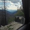
Does anyone know what is wrong with my pathy. When im crusin on the freeway it starts to sway. When i brake a little bit it goes away. What could be the problem?? Suspension? Thanks -Alex1 point
-
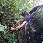
Hi R50 Forum, (2002 Infiniti Qx4 4x4) I was in the market for a older low cost wheeler. The current project was put on hold while an ex thought she would use my vehicle as leverage in our divorce. While the Toyota progress was stymied and on hold, I needed to find an affordable daily driver. I was looking for 4 wheel just in case she snaked the Toyota. Wheelin and daily driving this qx4 has been very satisfying and enjoyable. It's built tough and super capable. My interest in Nissan off roaders admittedly started with the Nissan xterra, although I've never owned one. My journey to find a lowish costing 4 wheeler produced this qx4 that's got me excited and also joining this forum. Ill be the one doing majority of the work on it. I’m not a mechanic but have done many vehicle installs and repairs. I'm working with a limited income so add ons start with functionality first and appearance last. I plan to focus on either a winch or locker next step. Done by me -Trim front bumper, remove air difuser, relocate air temp. Sensor, remove wiper fluid tank. -Installed CB radio, antenna and p.a. speaker -Removed front and rear sway bar Previous owner -lift -tires Your community seems to be welcoming and it’s appreciated. Thank you r50 guys for all the research and info you’ve compiled here! Chris Photos added 2/1/211 point
-
Different types and chemistries of battery do prefer different charge voltages. I set up an off-grid solar system recently and the charge controller had different modes depending on which batteries you were running. Flooded and AGM were similar, but different enough to have separate modes. The instruction booklet had a table with recovery, bulk charge, and float voltages for each type it supported. The dual battery controllers I've seen advertised have a similar feature, as does the cheap battery charger I've got at the shop (unlike the old style, which is just a transformer with a rectifier and no other regulation, and will happily boil the electrolyte out of a battery if you leave it running too long.) An old-school internally regulated alternator has one target voltage and charges as hard as it's able to maintain that voltage. If the battery is very low, and the alternator is very powerful, it's going to charge that battery hard, possibly harder than it wants. Newer stuff has "smart" alternators with the target voltage set by the ECU, so they can adjust the alt's output to suit the state of charge, engine load, phases of the moon, whatever. Whether the battery life and fuel economy (?) gains are worth this added complexity, I don't know.1 point
-
2020: 02_Pathy *pending official border1 point
-
Just saying Hi as a New Member. It was a suggestion to join from YouTuber Tyler Smith a very knowledgeable young man. Sure is nice to see a lot of members on here. I have a 1996 Pathfinder. Still looking for more info on what a Peak to Peak Edition is. Not sure if I have an LE,SE or XE or what it is and nothing on the trim or paper work that I could find. If you have info let me know. Going to start off with a lift kit and keep going from there. Thanks again I'm headed over to a FAQ.1 point
-
Finished the parking brakes on the Frontier today! I'm very pleased with how it turned out, far better than what I did on the Pathfinder. The other night I determined that the 300ZX brake kit wasn't going to work. The return springs were too short, as were the anti-rattle pins. Figuring that if the Passport parts worked, maybe a kit for the Passport would work, too. The kit arrived today and worked out perfectly...so perfectly that I'd say 100% of the kit pieces are compatible with the WD21 brakes. The parts on the left are from Carlson 17396 for the Passport (and several other Honda, Isuzu, and Acura vehicles 1994-2015), and the parts on the right are from Carlson 17418 for the 300ZX (and Q45, both 1990-96). The kits differ by the return springs at the top, and the anti-rattle pieces in the middle (pins, round springs, and retainers). The blue springs, red/orange springs, and adjusters are identical. Everything from the kit got used (well, except the c-clip and spring washer...didn't bother, wasn't needed). The return spring design is a little different from OE, but worked just fine. The proof: I'm stoked to have all that sorted finally. If you're ever missing parking brake parts for your disc brake-equipped WD21, find a Passport or Rodeo (or others). And now... Parking Brakes, Redux I mentioned in my post the other day that I was going to try a totally different approach by splicing the WD21 and D22 cables together. The results came out great. I've not explored if the exact same approach can be taken on the R50, but should be the same fundamentally. Since I did this on the D22, I'll try to explain it in R50 terms as best as possible. The pics, of course, will be of the D22 because I'm not even going to redo the R50 (I think I tossed those lines anyway). Specialty tools wise, I used: a hydraulic crimper like the one used in the original project — for crimping the wire stops and butt splice connectors lineman's pliers, or something suitable for cutting 1/8" steel wire rope (small bolt cutters would work, too) a knock-off Dremel with a flexible shaft and metal cut-off discs — for cutting off crimp rings and cutting the parking cable outer sleeve and pinch clamp (Oetiker) pliers — for tightening pinch clamps on the rubber boots and hoses used to protect the parking brakes (optional?) Hardware: 2x 1/8" ID wire stops (I was going to use aluminum ones, but ended up using copper ones instead) 2x 1/0 (or "0") AWG butt splice connectors (I bought some from a local True Value that still carries hardware assortments, but they're available on eBay) 4x-8x single pinch hose clamps (18.2mm to 21mm; McMaster 5435K31) (...also optional) 5/8" ID thin-wall rubber hose (to cover the connector and protect the line; the stuff I grabbed at the hardware store was a thinner wall for plumbing use and was sold by the foot) The parking brake cable is two main parts: an inner cable, and an outer sleeve. For this approach, we're only splicing together the outer sleeves. The inner cable remains fully intact, minus cutting the ends and crimping new wire stops on. Before cutting the outer sleeve, make 100% sure the inner cable is pulled out of the way (cutting the inner cable in the wrong place is definitely not a good thing). The rest of the cable is just rubber boots, tubes, and brackets used for protecting and attaching the cables to the truck. Nissan uses compression rings to secure the rubber on the cable. The outer sleeve is made up of a metal "tube" and a plastic/vinyl jacket. The tube is actually a thick spring, which is why it's both rigid and flexible. I recommend a Dremel and small metal cut-off wheel over other means. An angle grinder with a cut-off wheel should work fine, but might be a little overkill. Just be sure to not distort the core, since it is just a spring. If needed, use a reamer, or jeweler's file, or other deburring tool to clean the opening, since the inner cable will need to pass back through without snagging. The end should also be flattened (the piece in the pic was scrapped, so it wasn't cleaned up). The cable has a 10mm outer diameter. I initially tried a 2/0 AWG connector, but it was too loose. The 1/0 connecter was a perfect slip fit, not loose, and not tight. The parking brake cable is mounted to the backing plate by a metal "foot" that is crimped to the outer sleeve. We're leaving that crimped part intact and cutting several inches away from it. I did 10" for this application, but something a little shorter (6"?) would be better. Not too short, but not too long. This will make it easier to sheath the cable with another rubber hose. (Remember, it's far easier to shorten something than it is to lengthen it...so be sure to cut enough material to work it.) The process starts by breaking down the WD21 cables to get the foot. Technically, you could just caveman cut right through the entire cable without doing any prep-work here. All that needs to be done here is to salvage the "foot" off the cable with enough of the outer sleeve still attached, and to keep the spring. Everything else won't be needed (you can try reusing the hose, but I preferred buying new stuff). My approach was to: Cut the exposed inner cable at the very end of the cable, farthest away from the foot. Remove the inner cable from the outer cable. Keep the spring. Use the Dremel to cut all the compression rings (I made two cuts on opposites sides of the ring...made it easier to remove the ring halves than make one cut and fight to pry it open). On the end farthest from the foot, I slid the boot down and cut the outer sleeve. Remove all the hoses on the line, leaving about 3' of outer sleeve with the foot at the end. Maybe keep the boots if they're not trashed. Now, the process repeats on the truck's cables. Start by cutting off the wire stop at the very end of the inner cable (cut right up against the stop), the pull the spring off (doesn't get re-used). Now, this is where things get tricky. On the D22, there's a short (18") tube that protects the line and is in between the foot boot and another up the line. On the R50, I think the tube is a little longer and is held in place by the brackets. Obviously, this tube obstructs where you'll be cutting. If you want to salvage the tube, you'll need to loosen up enough things (such as the brackets) in order to slide the tube up, exposing the area of the outer sleeve to be cut. If you don't care about the tube, you can just cut through it, but you'll still need to cut back enough to expose the outer sleeve (you can always put a larger ID tube over it after it's spliced). From here out, take your time with measurements and cuts. Definitely measure thrice, cut once. If you cut even a little too short, it's hard to find any slack to make up for it. Take your time. Start by mounting the WD21 cable to the backing plate. Make sure as much of the R50 cable is routed and attached in its normal position along the trailing arms (in my case on the D22, attached to the frame and routed over the leaf spring). Bend the WD21 cable to contour the original path of the R50 cable, then mark a suitable position on the R50 cable to cut (wrapping tape around it helps). This should probably be about 6" from the R50 foot. Make sure you also leave enough space to slide any protective hoses up the cable so they can be slid down after crimping. BEFORE YOU CUT ANYTHING: Follow the cable to the middle of the truck, where they connect to the parking brake lever and tensioning mechanism. You must pull the inner cable out enough so that it won't be cut! You may have to pop a dust boot off of a mount to do so. Cut the R50 outer sleeve only. You may need to detach the cable from the trailing arms so that you have room to work in. Once cut, reattach the cable to the trailing arm, again routing it in its normal position. Bend the WD21 cable again to contour to the desired path, aligning it to the cut end of the R50 cable. Check and double-check the cut position on the WD21 so that it'll meet up tightly with the R50 end, then mark the WD21 cable. Detach the WD21 foot from the backing plate, then cut the sleeve. It may be wise to leave a little extra on the cut, since the cable can flex if it's a little too long. If it's a little too short, it could be a problem. Once both cables are cut, you can confirm the lengths by slipping the butt splice connector on them. Do not crimp it at this time; it's just a test fitment. It should end up like this (well, similar...this is the D22 of course): You can see in this pic the connector is not crimped and that I have already mocked up the boot at the end. At this point, there's a bit of an order-of-operations. You must have everything in place on the line before anything is crimped. That means any boots, pinch clamps, the butt connector, protective hoses...everything must be in place first. Once the butt connecter is crimped, nothing else can be added or removed to the line. In my case, I left (or created) enough slack to slide a longer piece of tube that will get slid down. Reattach everything to the truck. Bolt the WD21 foot on the backing plate, and R50 cables on the trailing arm again. Everything should be snugged up a little, too. The reason is that the cable must be in its normal resting state with it's all crimped together, otherwise you'll hate yourself later. You can also push the inner cable back through the sleeve from the middle of the truck now. If it jams where the cables meet, you can move the cables around to guide it through. Once everything is attached correctly and pieces are on the cable, you can crimp the butt connecter. The hydraulic kit has a "50" and "75" die for 1/0 and 2/0. respectively, but a "60" would have been better here. The 75 is too big, and the 50 too small, but the 50 needs to be used here. Don't max out the 50 crimp! Instead, feel for a stopping point on the hydraulic crimper before the dies meet—this is the point where the crimper is starting to apply excess pressure to the spring core. I imagine the crimper could surely collapse the core, which would be a very bad thing. So, crimp firmly, but carefully. It should end up like this: Keep pressure on the outer sleeve while crimping to ensure it stays fully engaged in the connector and doesn't create a gap. At this point, you can slide down any protective hose over the connector, or crimp the pinch clamps on the boots or elsewhere. Here's how mine turned out: This is the RH side, but the LH side turned out almost the same. Also, don't rely on any numerical measurements here when you change sides. Just because you cut 6" on the RH side, doesn't mean 6" will work on the LH side. Despite all the warnings above, the only thing I forgot to do was put a pinch clamp on the outer protective hose. Now...I put earlier notes that the pinch clamps were optional. It seems like Nissan used the compression rings on the rubber parts mainly to keep moisture and debris out. I'd say you could use hose clamps instead (I did on the LH when I forgot), but the pinch clamps were a nice substitute to keep an OE look. I wanted the protective hoses clamped specifically to keep water out of the line and eventually working its way into the butt splice connector. The ones I got from McMaster were perfect. I imagine you could also use CV boot band clamps, but these pinch clamps were far easier. As far as the rest of the setup goes, just take your time. Other key points and suggestions: Slack all the inner cable lines as much as possible before cutting the wire or crimping anything on. This includes loosening the parking brake cable adjuster from inside the truck. This way, you can tension everything up later (it'll surely need to be tensioned regardless, so leave room to tension it). After everything has been slacked, start with one side. The parking brake system is designed to equalize pressure to both sides, even when one side engages first. You need to determine which side might have less cable exposed to work with at the adjustment point I think the R50 is fairly equal. But on my D22, my RH cable was only shortened 1/2" (where the OE wire stop was cut off), while I needed to cut 2" off the LH cable, because of the way it's connected. Do one side first. Pull the inner cable enough so that it is taut. Use the parking brake shoe with the lever to confirm a suitable crimp spot for the wire stop. Cut the wire behind it (i.e., leave space for the wire stop), cut 1/2" of insulation off the cable end, then crimp the wire stop on (the wire stop must be on the steel portion of the cable, not the insulation). Fully assemble the parking brakes (shoes, springs, rotor, etc.) on this side. This is so you can confirm sufficient slack was taken up at the lever point. Now, do the other side. Be sure to pull the cable taut, then repeat the wire stop installation and parking brake assembly, including rotor. Adjust the tension on the parking brake lever according to spec (see FSM). Again, I'm super pleased with the results, but there was a LOT of "think" time to check and double-check (and even then, I still forgot that clamp). Definitely pay attention to the order of operations when cutting or crimping anything; it seems very easy to make a little mistake that will render a component completely useless and require a complete replacement, if not a bit more corrective work.1 point
-
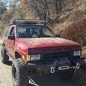
Hi all. Bill in Idaho. Not a big forum guy, but had to find a resource to help figure out mods and repairs. I haven't found anyone in ID to help me so glad I found this forum. 93' pathy with some great mods' by Kenny outta California. (think one of Steveo's buddies) SAS with the rock assault yota axle, coil overs, sliders, grizzly locker in the rear, etc. All done by Kenny fabricator guy and design ideas by a guy nick named 'Soup'. I was a noob to rock crawling/ overland - these guys helped get into it. I love it and LOVE my Pathfinder!
.jpg.a6294a1850e9234ae7d896296cf29898.jpg) 1 point
1 point -
Just an update on this, after 2 months mine R50 is running fine. If you go the wrecker route, make sure to tap the canister with a screwdriver handler and make sure nothing comes out. Take the time to dismantle and clear the the Purge volume control valve,it will take about 20 minutes to do right, get all the carbon flecks out of there. Use a small flashlight to make sure. I used a shop vac and a lot of duct tape to clear the lines, from the engine end and gas tank end. If you take your time this should get you up and running with minimal problems.1 point
-
Well from what i read in the frequently asked questions section I learned that my dead fuel and temp guages were almost definitely a result of a faulty voltage regulator. So i pulled out my dash cluster and had a look around. The voltage regulator (here forth referred to as VR) was pretty easy to spot, it's located in the top right corner when you turn the dash cluster around and are looking from the back. I gave it a quick test with my multimeter (black to negative of a new 9 volt battery, yellow to positive, blue to positive test lead of multimeter, and negative test lead to negative of battery) I found that the little bugger was only giving me about 3.5 volts, having followed the traces on the back of the cluster and finding out I need 8 volts going to the gauges, this VR is shot for sure. For reference the black wire is ground, blue is Vout (voltage out), and yellow is Vin (voltage in). With that I headed over to radioshack. As I'm perusing the component parts section I discover they only carry 5VDC VRs and 12VDC VRs. However given further investigation i notice they also have adjustable VRs. Great, so it's definitely do-able i'm just going to need a few extra parts. I end up getting the adjustable VR, a pack of 5 100 ohm 1/2 watt resisters (only need one), and a 1K ohm trimmer (basically an adjustable resistor up to 1k ohms), I also pick up a little 2"x2" PCB to put everything on. Now in order to get the VR to 8VDC I'm going to need to wire the 100 ohm from the adjust leg of the VR to the Vout leg, and the trimmer from the adjust leg to ground. The trimmer needs to be set at 540 ohms in order for the VR to put out 8 volts. Another important thing to note is that the trimmer has 3 legs, one of which is called the wiper (the back of the bag it came in will tell you which leg it is). The wiper needs to be shorted to one of the other two legs, it doesn't really matter which, and from then out it will act like a regular resistor except now it's adjustable. I wired that all up on the PCB and connected it back to the cluster, being sure each wire went to it's appropriate place, and popped the whole thing back in the pathy. Grab my keys and turn her on, and all of a sudden my fuel gauge springs to life! Turns out I got a little over half a tank. As i let her run and warm up, my temp gauge slowly starts to rise as well! Cool all fixed, on to bigger and better things. Like figuring out why she idles so high and sporadically after she does get warmed up.1 point
-
We would like to take a moment to welcome you all to the new home of the NPORA! Nissan Pathfinders Off Road Association (nissanpathfinders.net) With the apparent demise of the original (nissanpathfinders.com) we came to the conclusion that for the benefit of the entire NPORA community we needed to move forward and open up a new home site. Please excuse our mess, as it is still under development. We will be adding new content, expanding current pages and better defining what the site is and where we are headed with it... and of course adding Member Pages1 point
-
sounds like r50 rear lower arm bushes to me. know as the pathy shimey have a look at them and see if they are torn1 point