Leaderboard

Popular Content
Showing content with the highest reputation on 04/04/2019 in all areas
-
Congrats @PathyDude17! *Pending official border.4 points
-
Happy 4x4 day guys!! Make sure to go hit the trails today if you can!2 points
-
Quick update on the front springs. I did speak too soon saying there was no top out on the struts. Depending on where I drive I might go a full day without noticing it, but if I hit something like a pothole just right it will definitely do it. I know some people with the AC coils have reported no ill effects from long term top out, but I still don’t like it. It’s a pretty violent bang when it happens and I feel like it can’t be good. I ordered up a set of limiting straps earlier in the week and started mocking them up last night. I’ll share an update on how that works out once completed. Sent from my iPhone using Tapatalk2 points
-
I know somebody who heard about the hockey puck bumpstop trick and massively misunderstood...he just slipped 3 or 4 through the coil and leaves em loose. Anyways...that's another good one, if done right!2 points
-
For a company called 'Unique Wheels' I would expect something... unique, not just 100% knock off copys.2 points
-
After years of chatting about our own Pathfinder projects—and often, grumblings about having to make our own parts or hack together something—it’s become clear that Jacob (@TowndawgR50) and I (Patrick) have a common passion for our trucks. We’re always bouncing ideas around and sanity-checking each other’s work, ultimately realizing we have highly complementary skill sets that extend beyond working on trucks. We’ve also grown tired of a serious lack of aftermarket support for our trucks, especially when there’s an obvious demand to keep them on the road and make them more capable than they already are. To counter that, we’re teaming up to fill that void. That’s right: it’s time to turn a hobby into a business! In the weeks to come, we will be making more announcements regarding the status of the company (still working on the name!) and our product offerings. We’re still in the early stages of the company formation, and have some challenges ahead of us (most notably the 1,400 miles that separate us!), but we’re ready and stoked to get the word out there. If any of our individual projects have piqued your interest, then our collaborative efforts won’t disappoint. Our initial focus will be on subframe drop (SFD) kits, as this is the most important component required to move beyond 2” of front suspension lift. Unlike prior versions of kits that have existed, we intend to offer complete kits and à la carte components in multiple heights—including strut spacers—to support various lift configurations. Our particular focus is to provide high-quality finished products that simplify installation for the average DIYer (hint: strut disassembly not required), and without having to replace aftermarket components you’ve already purchased. While we won’t go into detail about all the products (and services) we’ve been discussing, we will tease that trailing arms and panhard bars (both in static lengths with poly bushings, and adjustable lengths with rebuildable joints), skid plates, missing link, and bumper brackets are on the product roadmap. That said, we’re looking forward to a productive 2019, so stay tuned!1 point
-
No issues! It’s a 98-01 thing only. Yours never had one.1 point
-
After reading about installation of an ammeter, I am dubious about its usefulness in a modern alternator-equipped vehicle. The Pathfinder's alternator is also capable of generating more than 60 amps, so that ammeter could get maxxed out if you actually use it. The most tell-tale sign of an electrical problem is often a voltmeter. We know that alternators generally output between 13.6 and 14.4 volts, and if the voltage is lower than that with the engine running, there's something wrong. That being said, if you intend to diagnose an electric drain when the engine is off because you frequently have a dead battery after sitting overnight, it's better to actually use a multimeter and insert its leads between the negative battery cable and the negative battery terminal to measure the current draw. A measurement above about 100 milliamps (0.1a) should be investigated.1 point
-
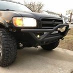
No, I think they were on the rear. Full size trucks have a different bump stop setup. heres a picture of my dad’s F150, this is essentially what I pulled off the JY truck1 point
-
I love that you know who it is haha. Clean build with the strangest butchery. I assume they were front bumpstops? Pretty sure those trucks are coil up front, but idk how many years back that's the case.1 point
-
I Know EXACTLY who that is lol. Jeep owners, am I right? As far as what model F250 they were, I can maybe go look, but it was just a frame left. I’m at the JY tomorrow pulling a part for someone else, so i’ll go check.1 point
-
Here's my cheap and as a joke bumpstop, a hockey puck which works well bolted to the perch Sent from my SM-G960U using Tapatalk1 point
-
I pulled bump stops off an old F250 at the JY, $3. They stacked nicely on top of my old bump stops. They’re about 1.5-2” longer. I would’ve used the top mounting location, but I snapped a bolt, so they’re anchored to the lower perch, which is probably functional but not ideal.1 point
-
Longer bolts (M8x1.25) and body lift spacers (3" diameter) is what I've heard being done.1 point
-
Great photos! You should get some of these printed1 point
-
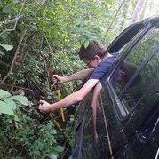
Alright time for some catch up, still on the road and visited CO, AZ, and NM after Utah. Notable places, Mesa Verde and Monument Valley Sent from my SM-G960U using Tapatalk1 point
-
Well, it's as done as it's gonna get before my CANVAZ trip this weekend. I will eventually put some plate up top and some additional brackets under the quarter panel for support. I've been pretty pleased with the cuts. My AZ flag apparently had some hidden lines that got cut, but I went with it. Cheapo MicTuning lights off Amazon are wired to the reverse lights...and make the OE bulbs look like garbage. I also made a new missing link and mid skid... Super pleased with the results. It slides on/off just like the front skid, and now all the hardware is matched for a single socket. ... I know this thread started off for front bumper brackets, but I've come a lot farther than expected. I'm still planning to go through with the front brackets for those interested, but still need another week or so to finalize a few things and put some numbers to things. I'm absolutely exploring options to make skids and missing link available, too. Stay tuned!1 point
-
Still pecking away at it... In hindsight, I wouldn't have made the corners stick so far back, and maybe not so low either. Still to-dos are finishing the other insert panels (waiting on the lights tonight to confirm the mounting pattern), and put some plate on top to get some flat surfaces. Right now it comes in at 62 lbs. It'll probably be able 75-80 when done. On a side note, I started sketching up a plate version of this with some wild dream about producing a DIY kit. Still a lot of clean-up to do on that idea.1 point
-
Today I picked up 600 lbs of steel plate...enough to make the initial 6 bracket sets...and some skids plates. I'm still debating whether that means front or mid skids. For sure, I plan to make a mid skid to match my front skid. There might be some other revelations along the way. For now, still focusing on the remaining V2 tweaks. I'm still dividing my time across several projects to build up some confidence using the plasma table. I've not fired it up for a few days, but this week I will be cutting out the brackets and other items for my rear(!) bumper, which I (finally!) started last week. The truck has been without a rear bumper for months now, and the goal is to have it done before CANVAZ. Lots of work left to do!1 point
-
Alright! I got the AC installed the other weekend, and it is GREAT! Fired up the plasma cutter to do some by-hand cuts last week, and tonight I cut my very first pieces on the plasma table! Nothing special, just some mounting tabs for a bracket to hold up a massive ventilation fan that @TowndawgR50 hooked me up with. Getting the rest of the ventilation pieces tomorrow, and will hopefully weld up the fan bracket and get things installed over the weekend. I think that's the last item on my list to complete the garage-to-workshop conversion...well, could use a TV in here, maybe move my mini-fridge from the other garage, some more lighting....anyway, details. Over the weekend, I also got around to converting all my original parts and some V2 modifications into the CAD/CAM application I was hoping to use for both my CNC router and plasma table. The application (Autodesk Fusion 360) is very frustrating, to say the least. Some issues are surely learning curve induced, and it might get me where I need to be in time, but I'm going to explore some other options first. Notably, it allowed me to cut my parts tonight, so at least I know we're heading in the right direction.1 point
-
Like Hawairish mentioned earlier, Ive started working with him on the design of these brackets. He sent me the data to punch out a set, using his current iteration, so I can start mock up on my rig and work with him on the R&D end. I have a chunk of time coming up and plan to push on this project so I can finally get rid of the XJ bumper and help however I can to get these on the market!1 point
-
Here's a daylight shot: One day, I'll actually start that rear bumper, giving me a better excuse to pull everything down and get it coated! We finally got some rain the other day...prior to that, it was fairly rust free. On the plus side, I finally started v2 redesigns this week on the bracket. I'm at a minor blockage rethinking where to put the shackle mounts due to other modifications, though. I'm currently planning to move them closer to the OE tow loops, about where the lowest bolt is in the pic. That would provide the necessary space for mounting a crossbar/receiver under the winch channel. I'm also playing with the idea of lowering the channel altogether, for those not wanting to find an alternate control box mounting position like I did...but it would lose the option for a receiver. I know this build has slow going, but we will get there... Not yet. The original plan was to have a batch done by my local steel shop, but we're fast approaching the time when I'll be able to cut these in my garage for less. Equipment arrives late July, hoping to be on my feet early August. That gives me time to make my design changes, set up shop, get material costs, get a new head-count on interest, and start cutting stuff. Exciting days to come!1 point
-
Not late, I'm just a little stalled for the time being. I'm trying to ramp back up for a v2 of the bracket, but too many other projects at the moment. Hoping to have a much better answer within a month. I still have all the pics, but my image host, Post Image, did something stupid with links. Checking with them to see if they have a better solution before I have to redo everything. Here's the abstract:1 point
-
I'm long overdue on a reply here! Unfortunately, I haven't been able to touch this project for several weeks due to all sorts of stuff, but this week is looking a little promising. Right now, I'm about 85% done with the bumper: I've been driving it around like this for a while, and well...it hasn't rattled off the truck, so I must be doing something right. What remains are mounting the winch solenoid box somewhere, and putting some sort of coating on. The former issue has been a pain...the control box is somewhat large and obnoxious, so I'll likely end up using my CNC router to create a mounting plate from 1/4" ABS sheet and mounting the box vertically in front of the radiator behind the grille, plus some other re-wiring to relocate the remote control plug. More work than I was hoping to do, but whatever. For the latter, I'm leaning towards using Monstaliner and one of their tintable kits, probably just their dark gray (not a fan of black). I'd love to go with an orange color (for bumper, sliders, tire carrier, and rear bumper when done), but I'm not really flashy like that...and there's a small premium on most colors. Of course, that 85% excludes a bunch of other smaller tasks, like blacking out the washer fluid reservoir and deleting the pre-airbox squid. I'm also trying to figure out lighting; might just go with 4 cheapo LED pods inside the angular openings. I've not welded up the skids, but I did make the necessary bends: I achieved my goal of making this a slide-on/off process. Just loosen the six bolts (4 under the radiator support and 2 under the crossmember) maybe 3/4" and slide forward. I may actually weld the two skids together, though that wasn't the original plan, but it'll work fine like that. Reason for wanting two pieces was to have 3/8" of steel plate under the support. With my existing mid-skid plate, I've also got additional layers under the cross member. I may also add some side wings for a little extra covering of. The ribs on the backside of the plate might be a little too close to the sway bar on articulation, but I may just test it out as originally planned. It may only make contact if my front end bottoms out, but when I replace my current OME MDs with HDs soon, that'll rotate the bar upward for more clearance. I can move the skids forward a little to add some clearance, too. .... I've been really slow on making progress towards getting the next set of brackets cut up, for several reasons. But, I've not lost sight of the project. My main concern is seeing a real-world application (mine) and making any corrections or improvements. The other thing is still avoid a repeat of the file snafus from the first set...too much rework on files. I intend to re-CAD my original drawings in another application, and that's just a matter of time becoming familiar with the application. The same application will be use when I get my CNC plasma table...oh yeah, I hinted at it previously, but it's official: I bought a CNC plasma table. I won't see it until June, though, and I'll need all the time until then to get a plasma cutter, air compressor, and electrical drops in the garage. I would like to have the 2nd set of brackets cut by the local shop still, just to not stall getting these out there. There will be a v2 design with the following changes, and I'm open to questions, concerns, and suggestions: Shackle mount depth: the shackle hole will move forward and protrude beyond the face of the bumper. I like the recessed location in general, but it presented some issues when trying to avoid blocking access. Hi-lift flat: one thing I wish I had incorporated was a simple flat spot for the tongue of a Hi-Lift to fit under. This might not be useful for all builds, but would be easy to incorporate. Shackle mount width and/or orientation: The current width is 1-1/8" (3x 3/8"), ideal for a 3/4" shackle. I don't want to change the width, per se, but the layered approach (pieces on each side of the main bracket) created some limitations when determining how to mount the bumper to the brackets. I may reduce the layer to two, giving 3/4" (2x 3/8") of shackle width, which actually seems pretty standard on other bumpers. Fewer attachment plates: the current design uses 3 separate plates for attaching a bumper face to the main brackets. I found this to be a pain, in terms of aligning everything and accounting for metal twisting from welding. The next design will have two plates (one per bracket) only. I will probably have a separate set of places specifically for creating a receiver tube attachment. General main bracket: couple small changes here and there regarding cuts, shape, etc. Hopefully more to follow this week...1 point
-
Sorry, Saturn, time hasn't been on my side since my last post. But, am still working on clean-up. I'm also wanting to wait just a little longer until I can get more of my bumper going so that I can get a better idea on the changes. Progress there has been slow, too, but it's coming together. I should clarify that mine likely won't be a true snorkel by any means, but rather a duct re-route somewhere under the fender. There are some universal flex ducts (and not the stuff for clothes dryers) that I was thinking about, but I've not looking into routing options quite yet. I just need something to replace the wonky pre-airbox-airbox. Not necessarily this, but like this: https://www.amazon.com/dp/B01J3JGDM2 I remember seeing this approach and thought it was clever. I'd rather not modify the airbox if I can avoid it, but my goal is less for water intrusion and more for getting rid of that ugly pre-box. It's something I can look into! ... As a small update, things are going slowly. The core bumper is together, still need to tack up the tubes under the channel and do the wings. I toasted my metal-cutting saw blade the other day, so I'm dragging my feet to do the remaining compound cuts I need before I break down and buy either another blade or proper chopsaw. Not sure what it is, but this .120" tube has been exceptionally brutal to both my saw blade and the cut-off wheels I've got, noting that the same blade has cut through .250" steel without issue before. I guess that's a good sign for the bumper, though. Haven't really paused long enough to take more pics than this, unfortunately. But since this pic was taken, I've filled in more welds and smoothed up the tube ends under the fender. Made no progress over the weekend due to being out of town.1 point
-
The O2 sensors were good. I asked a buddy who is an auto tech if he had any ideas. He said he thought it sounded like the throttle position sensor was going bad. It seemed easier and cheaper than messing with the distributor so i replaced the TPS. I took it out for a 30 mile ride to test it, i even took it on a mountian road so that it would have a fairly large load on it. I had no problems, so I believe this was the fix...if it comes back i will give an update.1 point