Leaderboard


Popular Content
Showing content with the highest reputation on 08/16/2018 in all areas
-
If looking at wheels studs, I posted some Dorman numbers here: link I'm a fan of stock wheels, too, which is why I went with spacers on longer studs. I've been using the front and rear studs from that post for several years on 1/4" and 1/2" spacers. No issues, though I did also put it in some nylon spacers on the studs to center the wheels spacers better.2 points
-
Thought I'd consolidate some notes, since a lot of people run wheel spacers and seem to want/need longer wheel studs. As mentioned in another post, I replaced the front studs on my 2004 Pathfinder SE with rear studs, which are 3/8" (9.5mm) longer, to run 1/4" wheel spacers. Summarized from Dorman's catalog (link) and cross-referenced at RockAuto (and sorry if this table comes out all jacked up): Dorman Knurl Diameter Thread Under Head Length RockAuto Application P/N in mm in mm 610-240 0.512 13.00 M12-1.25 1.260 32.00 87-04 Pathfinder (front) 610-320 0.505 12.83 M12-1.25 1.634 41.50 87-04 Pathfinder (rear) 610-403 0.508 12.90 M12-1.25 1.791 45.49 93-95 Infiniti J30, 93-98 Nissan Quest 610-295 0.508 12.90 M12-1.50 1.476 37.49 Misc. Hyundai/Kia, Mazda 610-507 0.512 13.00 M12-1.50 1.764 44.81 Misc. Hyundai/Kia, Mazda 610-410 0.508 12.90 M12-1.50 1.811 46.00 Misc. Hyundai/Kia, Mazda 610-409 0.508 12.90 M12-1.50 2.205 56.01 Misc. Hyundai/Kia, Mazda The options above should allow running a 1/2" spacer up front (use J30/Quest studs), and 1/4" at all corners (610-410 up front and 610-409 in the rear) with a different thread pitch. I think most people are just running spacers up front, though. If you pair the longer length studs to your wheel spacers (i.e., 1/2" longer for 1/2" spacers), your stock lug nuts will work, but I recommend longer (and/or new) lug nuts anyway. You'll obviously need them if you change thread pitch. Longer nuts are not to increase thread contact, but instead so the wheels can be installed if the spacer needs to be removed. Stock nuts are acorn style and either 29mm or 35mm. Not shown above is knurled shoulder length which, for the most part, is negligible. The wheel hub thickness and wheel nut seat depth will consume all of this, even without a spacer. However, some could be too tall without a spacer (possibly 610-409 with a 1.14" shoulder). Should length should be at least the thickness of the wheel hub, so double-check the Dorman catalog. If you have steel wheels, the material at the nut seat is likely also thinner than aluminum wheels, so keep that in mind, too. Studs and lugs at all corners is about a $60 project and a few hours of work. I used a $15 ball joint separator from Harbor Freight to press the lugs out, and an open-ended lug nut (Dorman 611-065) with a thick washer to seat them. The front wheel hub assembly will need to be removed from the truck. For the rear, a big hammer and a drift punch should unseat them (but it's been a very long time since I did this on my Frontier). You'll obviously want to confirm your particular application, but hopefully this is a good starting point.1 point
-
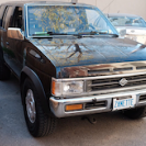
I copied this over here from Expedition Portal. At this stage this forum is probably more appropriate for the build since I am bringing the vehicle back to mechanically sound operation. I am looking for some 16x8" wheels that look good and have the proper backspacing for 265x75x16 tires. Dean (Xplorx4), I really like your rims. What kind are they? Dimensions? About a month ago I started looking at a cheap reliable vehicle capable of being built up as an overland rig but retaining the ability to get me back and forth to work (when needed) and could maintain a decent cruising speed on the highway. I had always wanted a later model Pathfinder with the VQ and a manual transmission, but cannot spend a ton of money. As luck would have it I found a 2002 5spd MT with a blown engine, but otherwise was in good condition for a reasonable price. I contact the owner and planned on going out to pickup the Pathfinder the next weekend. We just got back from the trip to last night and today I began work on the new to me Pathfinder.The plan:This vehicle has a lot of miles on it and although the unibody is in amazing condition with no rust I don't know what condition the mechanical are in, except the engine, which is completely blown. Step one is to get the engine, transmission, transfer case and driveshafts out. The transmission and transfer case will be disassembled, inspected, repaired if needed, and reassembled. The driveshafts will get u-joints and and be balanced. After the drivetrain is reinstalled and all fluids changed I will move on to the brakes, wheel bearings and suspension. Once funds are available I will be installing a 2" coil lift, wheels and tires, arb style bumper, lockers, sliders and skids. The goal is to keep weight down so that drive-ability is not lost.Known Issues:Right now the only two known issues besides the blown motor is that the rear windows will not roll down with the driver's switch or the rear window switches and the exhaust system past the largest muffler is completely shot.Current Status:Right now I only have to remove the upper engine wiring harness, bellhousing bolts and motor mounts before the engine can be removed. I will probably go ahead and pull the transmission/transfer case as a unit before removing the engine.1 point
-
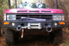
Holy crap TowndawgR50 , that picture looks awesome. I am leaning toward these rims and use some 1/4" spacers. Although I hate the idea of spacers, 1/4" spacers with slightly longer studs doesn't scare me too bad. At this width they are just big flat washers. Looks like the Summit warehouse has wheel studs that are 12mm longer in stock, too. There is something about the big spokes and factory-ness of the wheel that makes me O.C.D. not burn so badly.1 point
-
FYI, if the lifters are a little ticky for the first bit, let them pump up.1 point
-
That looks great! I have been offline because my old computer crashed!! Built a new one and good to go!1 point
-
Yeahh!!! I’ll bet that’s a relief!1 point
-
The #@$% thing is in there. Sent from my iPhone using Tapatalk1 point
-
Banned for making decisions based on a rock band with bizarre costumes1 point
-
Maybe it was only economical on some of the rarer colors? Maybe regional, or even by manufacturing plant? I’d be curious to know the reason since it seems like extra work.1 point
-
Drive by wire (03-04) is one thing I hate about the truck. Stupid codes that disable the truck, plus "non-serviceable" throttle body and pedal. I had a P2135 (Throttle/Pedal Position Sensor/Switch "A"/"B" Voltage Correlation) that put my truck into limp mode maybe 5 times randomly over the course of 2 years, and caused random super-light surges that wouldn't throw codes (but would cancel my cruise if set). The proposed solution was to replace the throttle body. Rather than drop $150, I made the unit serviceable by drilling out the rivets then cleaned all of the contact points. No issues since. What Citron and Slartibartfast mentioned is what the FSM says, but I'd definitely pull the pedal and take it apart to see if any of the sensors can be cleaned. If the sensor has markings, you may also want to check Digi-Key for a replacement component rather than a whole new pedal, if you have the means to repair it (and if the switch can even be replaced). I did something similar for the shifter release switch on my transmission...$1 exact replacement part and some soldering.1 point
-
IIRC the last two years of the R50 had drive by wire. My dad's '03 did. It was one of the things I didn't like about that truck. I had a look at the FSM and the short answer is to try what Citron said. The sensor's got two separate pots in it, presumably so they can't both fail at once, and they're wired straight to the plug so that you can actually test them. Unhelpfully, the manual does not list their resistance, only their voltage outputs with the key on, engine off, MT in first or AT in D (no idea why). The first pot has two blue wires and a black/red wire, the second has a white with red, a red, and another blue wire (was there a sale on blue wire?). Sensor 1 (one of the blue wires, the one that's not steady 0v or 5v) should be 0.5 to 1v (measure its voltage to body ground, not to one of the 0v wires, apparently the ECU doesn't like that) with the pedal released, 3.9 to 4.7v with it floored, and sensor 2 (the red wire) should be 0.15 to 0.6v released and 1.95 to 2.4v floored. The graph shows straight lines, so yeah, if one of them drops out or bounces around then you've found your problem. Looks like you can also check all of this through OBD live data (SEN1 , SEN 2, and CLSD THL POS), but the ECU tweaks the numbers on one of them for some reason. If you do replace the sensor, the manual says to do three (!) different relearn procedures afterwards. All this starts on EC-708 of the '03 manual. I'd want to see if the sensor can be disassembled and cleaned. Maybe there's just some schmutz in there that a wiper's riding up on, and a shot of contact cleaner would resolve the problem without having to teach the computer how to tie its shoes again afterwards. Good luck!1 point
-
The R50 is fly by wire, not throttle cable? If so, you should be able to disconnect the plug at the pedal, put a meter across the potentiometer, put it on ohms. Press the pedal with the car off, and see if you have a smooth change. Or backprobe the plug with everything in service and car running and actually watch the voltage. It should be smooth, not jerky and no flat spots. That should tell you if the pedal is actually bad. I hope that makes sense? It does in my mind.1 point
-
+1 on the waterproof heat shrink. Also consider soldering the joints. Sent from my iPhone using Tapatalk1 point
-
If the splices are done properly, the rest of the circuit shouldn't even know they're there. Make sure you waterproof them. I use shrink wrap that's got some sort of hot glue stuff inside that melts and seals the joint when you shrink the tubing.1 point
-
This is why the forum is great, CORRECT and mathematically logical answers.1 point
-
It's in progress, I guess I'd say. My plasma table is here and assembled, and early (maybe mid) August still seems reasonable to have the shop ready.1 point
-
Like Hawairish mentioned earlier, Ive started working with him on the design of these brackets. He sent me the data to punch out a set, using his current iteration, so I can start mock up on my rig and work with him on the R&D end. I have a chunk of time coming up and plan to push on this project so I can finally get rid of the XJ bumper and help however I can to get these on the market!1 point
-
Here's a daylight shot: One day, I'll actually start that rear bumper, giving me a better excuse to pull everything down and get it coated! We finally got some rain the other day...prior to that, it was fairly rust free. On the plus side, I finally started v2 redesigns this week on the bracket. I'm at a minor blockage rethinking where to put the shackle mounts due to other modifications, though. I'm currently planning to move them closer to the OE tow loops, about where the lowest bolt is in the pic. That would provide the necessary space for mounting a crossbar/receiver under the winch channel. I'm also playing with the idea of lowering the channel altogether, for those not wanting to find an alternate control box mounting position like I did...but it would lose the option for a receiver. I know this build has slow going, but we will get there... Not yet. The original plan was to have a batch done by my local steel shop, but we're fast approaching the time when I'll be able to cut these in my garage for less. Equipment arrives late July, hoping to be on my feet early August. That gives me time to make my design changes, set up shop, get material costs, get a new head-count on interest, and start cutting stuff. Exciting days to come!1 point
-
I was going to get the fan from Amazon for $329. But when I decided to take Monday off and try to get it done, I started calling around to all the local distributors on the Flex-A-Lite page hoping to find one with it in stock. None had it available or knew what I was talking about until I got to the very last one. It was C&D Automotive in Fort Worth https://www.facebook.com/pages/CDs-Performance-Automotive/152463154904312. The lady at the desk, maybe Cindy..., was very nice and helpful. She found them for me at a new warehouse in Flower Mound and arranged for me to do a customer pickup, so I could get it the same day. And they were only $10 more than Amazon. I'll try to get some pics this week if the weather cooperates. I was going to do it today, but I spent the whole day rewiring my stereo, and messing with my A/C to figure out why the temp control knob quit working. The plastic bracket that holds the cable broke off, and I broke the air control cable bracket removing that one, and the back frame has another crack in it. So I'm just going to suck it up and pay the $144 for a new one from Courtesy Nissan.1 point